


Parts List
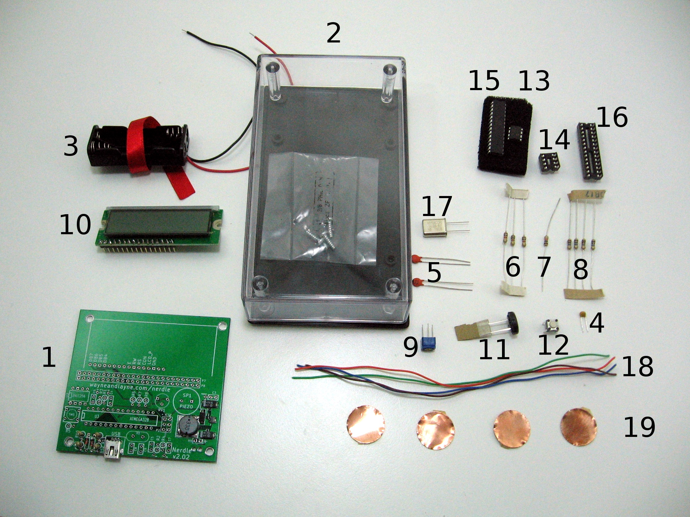
- (1) Nerdle Printed Circuit Board – PCB
- (1) 5.6″ by 3.25″ Plastic Case – Case
- (1) 2x AA Battery Holder – BT1
- (1) 0.1uF Ceramic Capacitor – C3
- (1) 22pF Ceramic Capacitors – C8, C9
- (1) 1K ohm Resistors – R6, R7, R8
- (1) 10K ohm Resistor – R5
- (1) 10M ohm Resistors – R1, R2, R3, R4
- (1) 10K ohm Potentiometer – RV1
- (1) 16×2 Character Liquid Crystal Display (LCD)
- (1) Piezo Speaker – SP1
- (1) Push Button – SW1
- (1) 24LC256 EEPROM Memory – U2
- (1) 8-DIP Socket – U2
- (1) AtMega328p Microcontroller – U3
- (1) 28-DIP Socket – U3
- (1) 16 MHz Crystal – X1
- (1) Wire
- (1) Copper Touch Pads
What does each part do?
A professionally-made PCB is the key to many successful projects. The Nerdle PCB is a fully-custom design with two signal layers.
The case holds the assembled circuit boards, and provides a place to attach the copper pads for the buttons.
The battery holder holds the batteries and connects them together to the rest of the circuit.
0.1uF Ceramic Capacitor (Back to list)
The 0.1uF ceramic capacitor is used in the power supply. It helps smooth the power fluctuations and ripple from the power supply.
22pF Ceramic Capacitors (Back to list)
The 22pF ceramic capacitors are used with the crystal to provide a low-noise, accurate timing signal to the clock of the microcontroller.
1K ohm Resistor (Back to list)
The three 1K ohm resistors are used to isolate the LCD from the microcontroller if an external programmer is being used.
10K ohm Resistor (Back to list)
The 10K ohm resistor is used to keep the microcontroller turned on. It is bypassed when the button is pushed, which then makes the microcontroller reset.
10M ohm Resistor (Back to list)
The 10M ohm resistors are used to provide one half of the RC circuit for the capacitive touch buttons.
10K ohm Potentiometer (Back to list)
The little blue rotary potentiometer is used to adjust the contrast of the LCD display. Turn it one way to get a darker display, and turn it the other direction to get a lighter display. Start it out somewhere in the middle and adjust for the ambient light.
16×2 Character LCD display (Back to list)
The 16×2 character LCD display is used to show characters. It has 16 columns and 2 rows. This display is HD44780 compatible. They can mostly only display characters (not graphics) but there are a few “open” characters that can be customized.
The piezo speaker is used to create noise in Nerdle. When the device beeps, it’s due to the microcontroller applying a square wave of 0 and 5 volts across the leads of the piezo speaker.
The piezo speaker contains a tiny piece of ceramic that exhibits the piezoelectric effect. This means that when the ceramic is flexed, it generates a voltage, and when a voltage is applied across it, the ceramic flexes. This crystal is attached to leads and placed inside a small plastic resonant chamber. This resonant chamber makes the sound louder.
This piezo speaker is direct-drive, which means that something outside of the speaker has to generate the frequency that the piezo will buzz at. Self-driven piezo speakers have some circuitry in them that lets them buzz themselves when powered.
The push button is used to reset the microcontroller. When Nerdle is plugged into a USB port, pressing reset puts the device into the bootloader, where it is ready to receive a new program over USB. To leave this mode, either upload a new program, or press the button again. If Nerdle isn’t plugged in to USB, pressing the reset button restarts the program.
The 24LC256 chip is an EEPROM chip, or an “electrically erasable programmable read only memory” chip. It provides 256 thousand bits, or 32 kilobytes of storage. This also means it can store 32 thousand characters. The microcontroller communicates with the chip via I2C, a simple protocol for connecting two embedded devices together.
28-DIP, 8-DIP Socket (Back to list)
A socket is a way to connect a chip to the PCB without soldering the chip directly. By soldering the socket on the board instead, there’s no possibility of overheating the chip with the soldering iron. The chip can also be removed or replaced without soldering.
AtMega328p Microcontroller (Back to list)
The AtMega328p is a re-programmable microcontroller used to coordinate the rest of the Nerdle. It has a “bootloader” that can accept programs via USB. It runs firmware which was written in the C programming language, and can be reprogrammed with the Arduino software.
The crystal provides the clock frequency for the microcontroller. This clock frequency determines how fast each instruction of the program runs.
The wire is used to connect the capacitive touch pads to the PCB.
The pads are self-adhesive copper circles. During construction of the kit, the pads are stuck to the inside of the clear case, and wires are soldered from the pads to the circuit board. These pads create one half of a primitive capacitor. When your finger touches over the pad, through the plastic case, your finger becomes the other half of the capacitor. This changes the electrical characteristics of the RC circuit connected to the microcontroller — the resistor (R) is the 10M ohm resistor for that button, and the capacitor (C) is created with the copper pad, the plastic case, and your finger. The microcontroller repeatedly measures the electrical characteristics of this circuit, and the change caused by your finger is recorded as a button press.