Blinky Flasher sketch for Arduino IDE
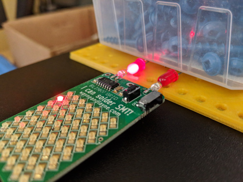
We recently started selling pre-assembled Blinky kits. As part of the manufacturing process, we really want to test out the optical programming process, to ensure that all the parts are working correctly. It would be inconvenient to dedicate a computer just to run the Blinky Programmer webpage to test each kit, so we decided to build a dedicated Blinky Flasher using an Arduino and two LEDs.

Here’s the simple sketch that transmits the pre-loaded data through the two LEDs. The code is also posted to our GitHub repository too.
/* Blinky Flasher
 * This sketch runs on an Arduino or compatible, with two LEDs.
 * It outputs the optical Clock / Data flashes to reprogram a blinky kit.
 *
 * Comment/uncomment one of the bytes[] definitions below to choose between:
 * 1. Original messages loaded into a Blinky Grid kit
 * 2. Original messages loaded into a Blinky POV kit
 * 3. Some other byte stream from the Blinky Programmer webpage:
 *    https://www.wayneandlayne.com/blinky_programmer/?debug
 *    Press 'Go' and then copy/paste the numbers from the `xmit_data` box
 *    into the bytes[] array below.
 *
 * The bytes are flashed-out once at power-up, then it stops until reset.
 * When it's done, the Arduino's built-in LED will start flashing.
 * Press the reset button to reset the Arduino and retransmit.
 *
 * More details about the Blinky message structure, framing, and transmission:
 * https://www.wayneandlayne.com/projects/blinky/design/#message
 *
 * Written by Matthew Beckler and Adam Wolf, for Wayne and Layne, LLC.
 * To the extent possible under law, Wayne and Layne, LLC has waived all
 * copyright and related or neighboring rights to Blinky Flasher.
 * This work is published from: United States.
 * More details: https://creativecommons.org/publicdomain/zero/1.0/
 */

/* Adjust these defines to match your LED connections.
 * This sketch assumes that HIGH output turns on each LED. */
#define PIN_CLOCK 14
#define PIN_DATA 16

/* Adjust this define to change the delay between LED state changes.
 * We've had reliable transmission with this set to 20. */
#define DELAY_MS 20

// The setup function runs once when you press reset or power the board
void setup() {
    // initialize digital pin LED_BUILTIN as an output.
    pinMode(LED_BUILTIN, OUTPUT);

    pinMode(PIN_CLOCK, OUTPUT);
    pinMode(PIN_DATA, OUTPUT);

    digitalWrite(PIN_CLOCK, LOW);
    digitalWrite(PIN_DATA, LOW);


    Serial.begin(9600);
}


// These are not message_data, they are xmit_data (including intel hex record framing)


// grid:
byte bytes[] = {16,0,0,6,8,230,14,170,85,170,85,170,85,170,85,170,85,170,85,170,74,16,0,16,6,85,10,11,17,14,21,21,24,41,32,24,27,21,13,234,7,128,16,0,32,6,4,98,97,9,97,98,4,10,11,32,10,34,23,14,38,21,114,16,0,48,6,10,34,23,14,222,14,48,72,68,34,68,72,48,48,120,124,191,16,0,64,6,62,124,120,48,10,34,11,21,18,23,20,34,41,16,27,18,55,16,0,80,6,13,41,18,28,41,10,41,28,22,10,27,29,41,21,14,13,13,16,0,96,6,41,22,10,29,27,18,33,37,10,40,11,21,18,23,20,34,0,16,0,112,6,41,16,27,18,13,41,32,10,28,41,22,10,13,14,41,11,0,16,0,128,6,34,41,32,10,34,23,14,41,10,23,13,41,21,10,34,23,214,16,0,144,6,14,37,10,60,11,21,18,23,20,34,41,16,27,18,13,41,198,16,0,160,6,18,28,41,27,14,25,27,24,16,27,10,22,22,14,13,41,217,16,0,176,6,11,34,41,17,24,21,13,18,23,16,41,18,29,41,30,25,168,16,0,192,6,41,29,24,41,34,24,30,27,41,28,12,27,14,14,23,37,108,0,0,0,1,255};


// pov:
//byte bytes[] = {16,0,0,6,6,145,16,24,60,62,31,62,60,24,0,96,240,248,124,248,68,16,0,16,6,240,96,0,33,10,11,21,18,23,20,34,41,25,24,31,145,214,16,0,32,6,14,128,64,32,16,8,4,2,1,2,4,8,16,32,64,17,46,16,0,48,6,7,17,14,21,21,24,41,41,253,14,170,85,170,85,170,85,248,11,0,64,6,170,85,170,85,170,85,170,85,211,1,170,53,0,0,0,1,255};


// other:
//byte bytes[] = {8,0,0,6,1,30,5,17,14,21,21,24,109,0,0,0,1,255};


// the loop function runs over and over again forever
void loop() {
    Serial.println("");
    for (unsigned int byix = 0; byix < sizeof(bytes); byix++) {
	Serial.print("\n");
	Serial.print(bytes[byix], HEX);
	Serial.print("  ");
	for (signed int btix = 7; btix >= 0; btix--) {
	    // set data to black/white
	    if (bytes[byix] & (1 << btix)) {
		Serial.print("1,");
		digitalWrite(PIN_DATA, HIGH);
	    } else {
		Serial.print("0,");
		digitalWrite(PIN_DATA, LOW);
	    }

	    // delay a few ms
	    delay(DELAY_MS);


	    // change clock state
	    digitalWrite(PIN_CLOCK, !digitalRead(PIN_CLOCK));


	    // delay a few ms
	    delay(DELAY_MS);
	}
    }


    // all done
    digitalWrite(PIN_CLOCK, LOW);
    digitalWrite(PIN_DATA, LOW);


    while (1) {
	digitalWrite(LED_BUILTIN, HIGH);   // turn the LED on (HIGH is the voltage level)
	delay(100);
	digitalWrite(LED_BUILTIN, LOW);    // turn the LED off by making the voltage LOW
	delay(100);
    }
}


