


Build Instructions
Step 0: Gather Materials
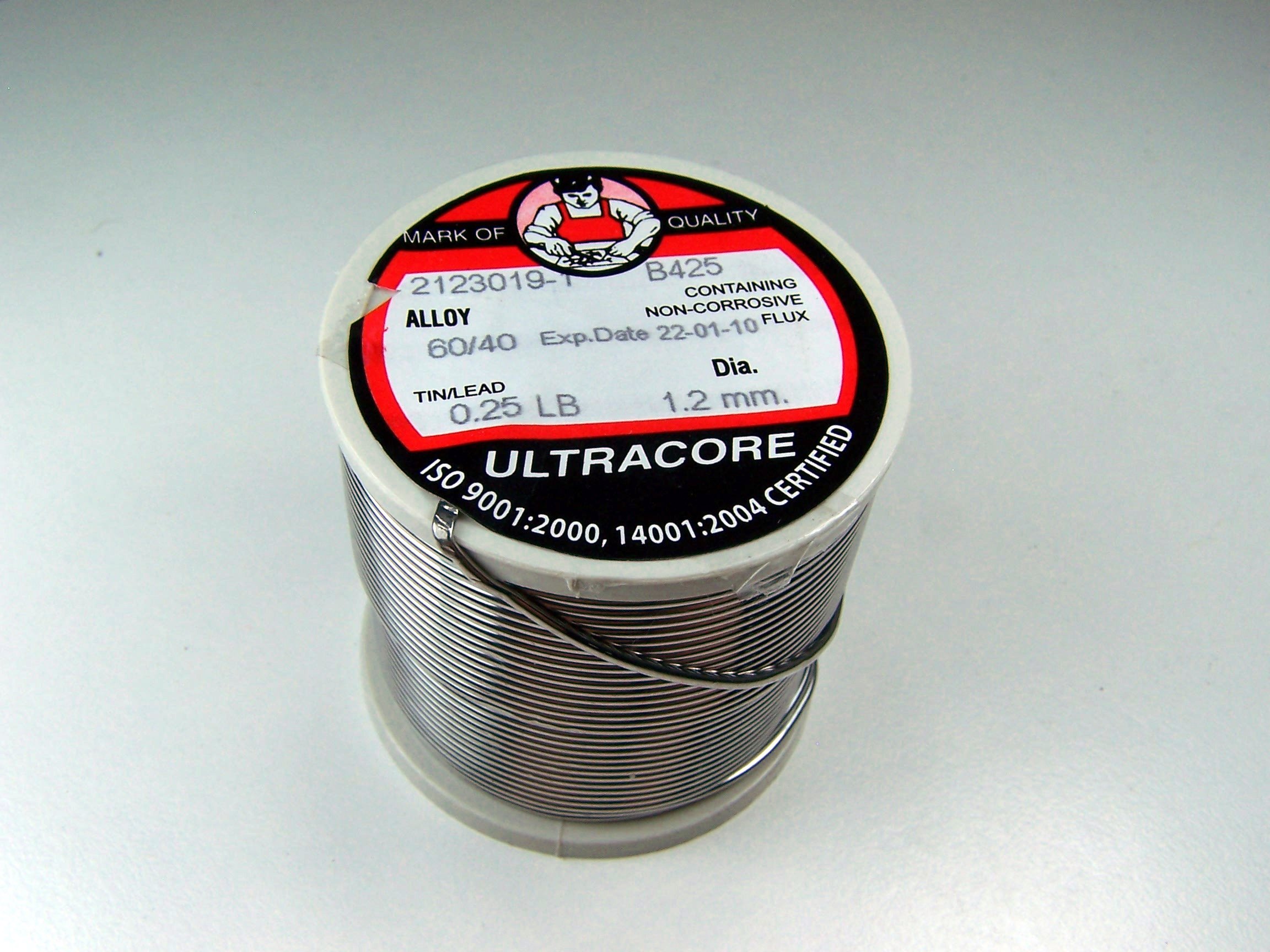
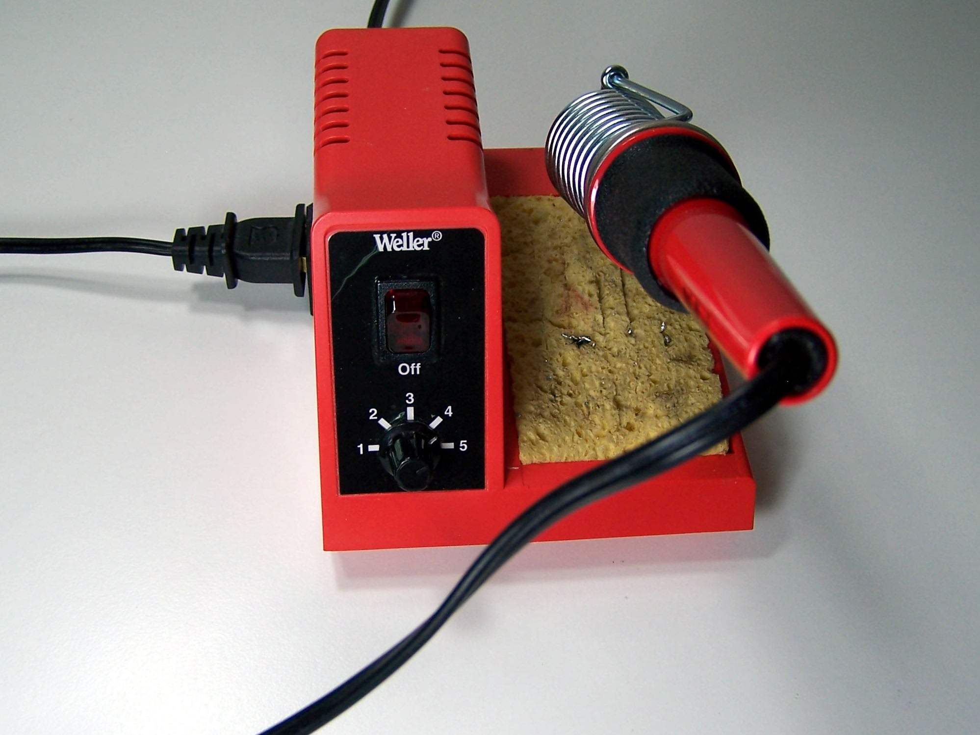
To build Nerdle, you will need a few common tools for soldering and electronics work. A soldering iron and solder are the most important tools. A higher-quality, adjustable temperature iron will be easier to work with and give higher quality results, but an expensive iron is not required. Do not use a ColdHeat iron, but any other pencil-style iron should be fine. Any standard rosin-core solder for small electronics will work just fine. Avoid solder made for plumbing or welding!
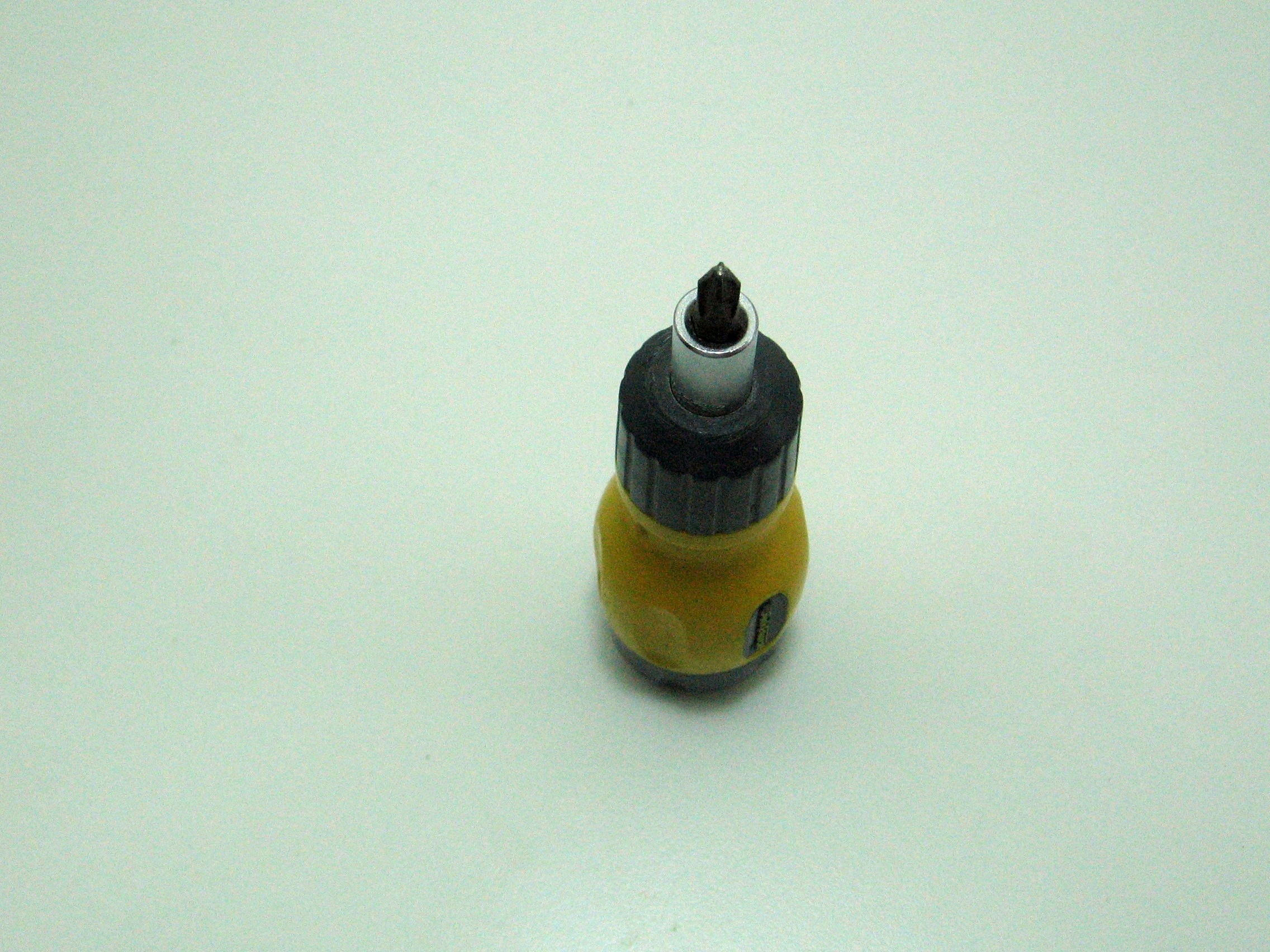
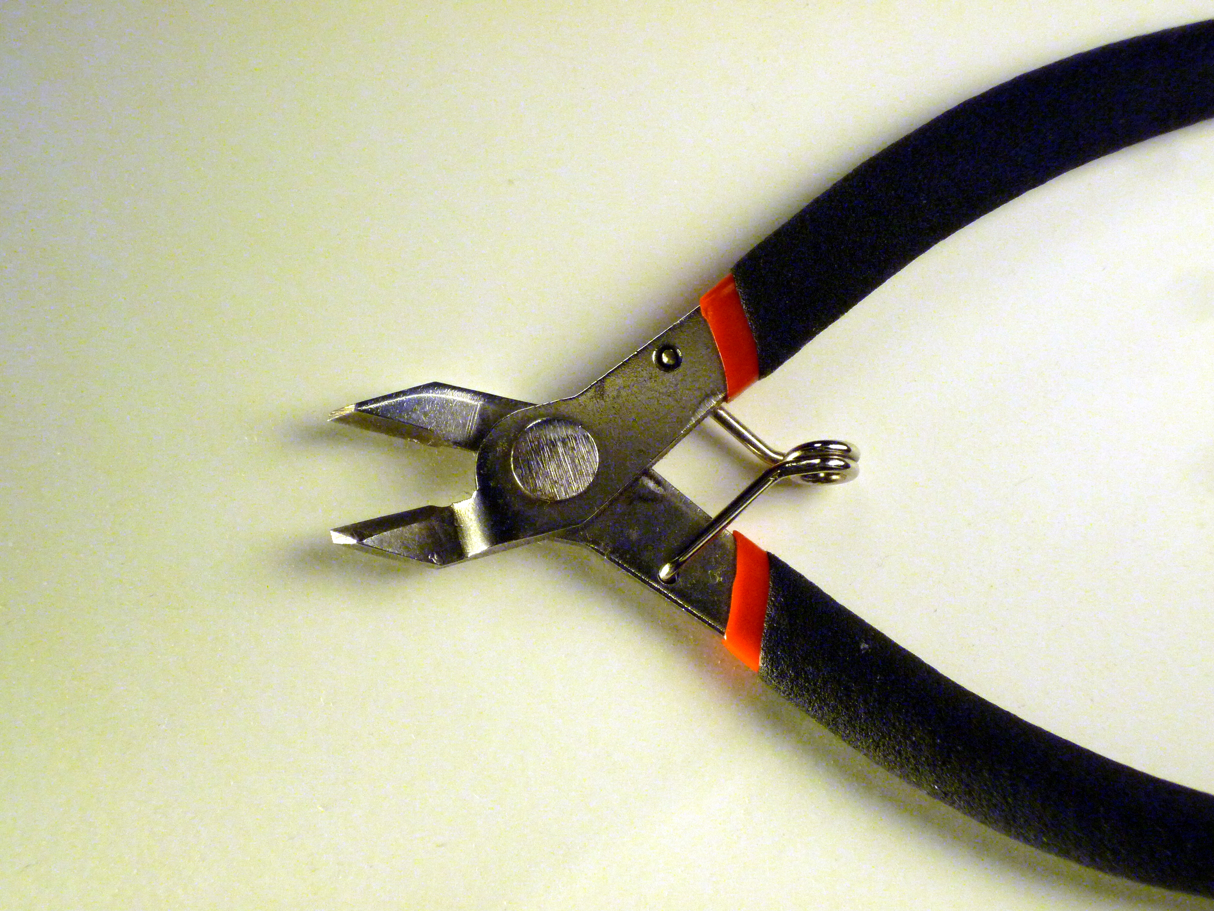
A diagonal pliers is useful to trim the excess leads off components. A Phillips screwdriver is also needed to attach the nerdle to the case.
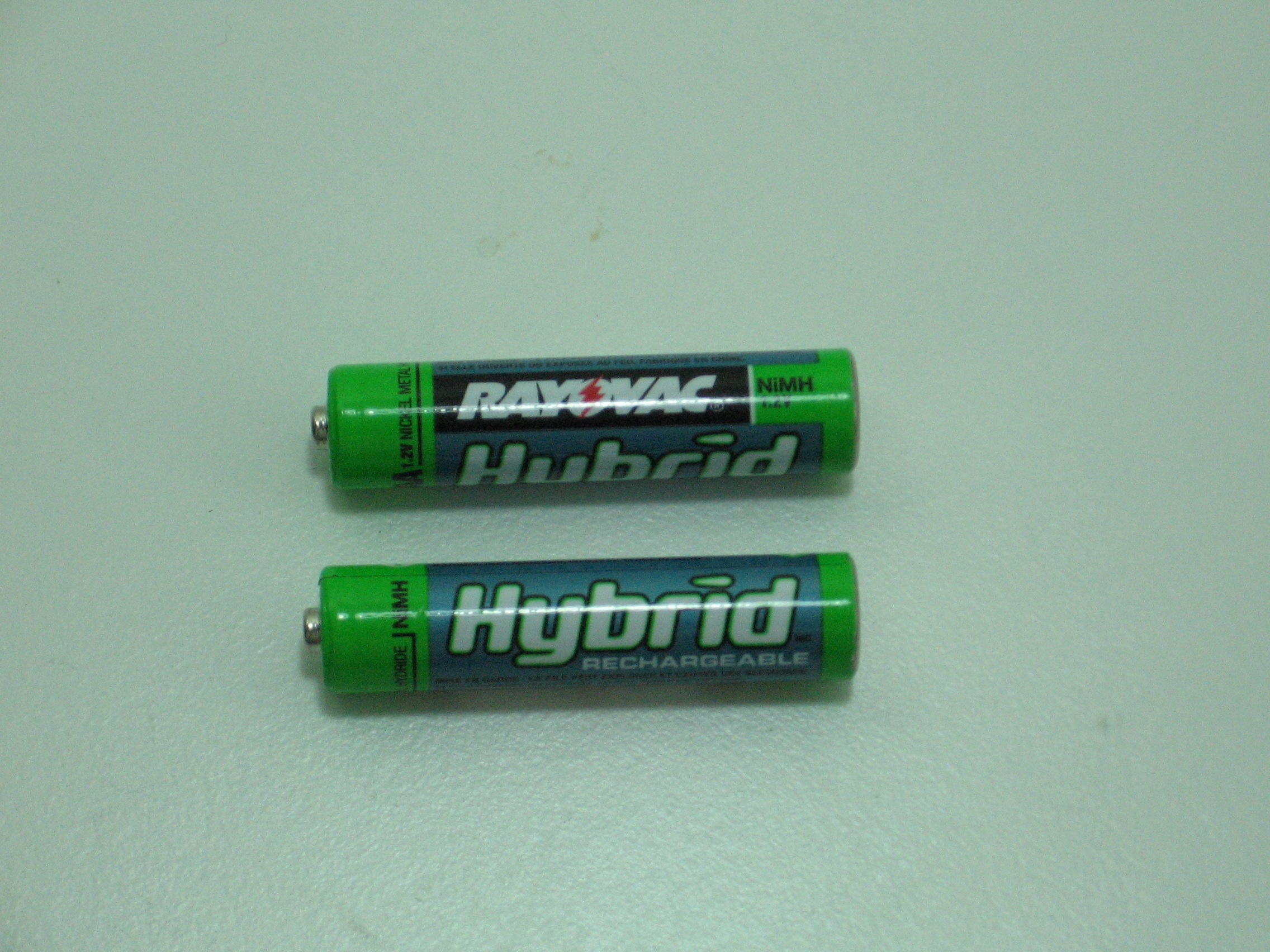
To power Nerdle, you’ll need two AAA batteries. To check your work, you’ll need a multimeter that can measure resistance and DC voltage. Ours looks like this, but they come in all shapes and sizes.

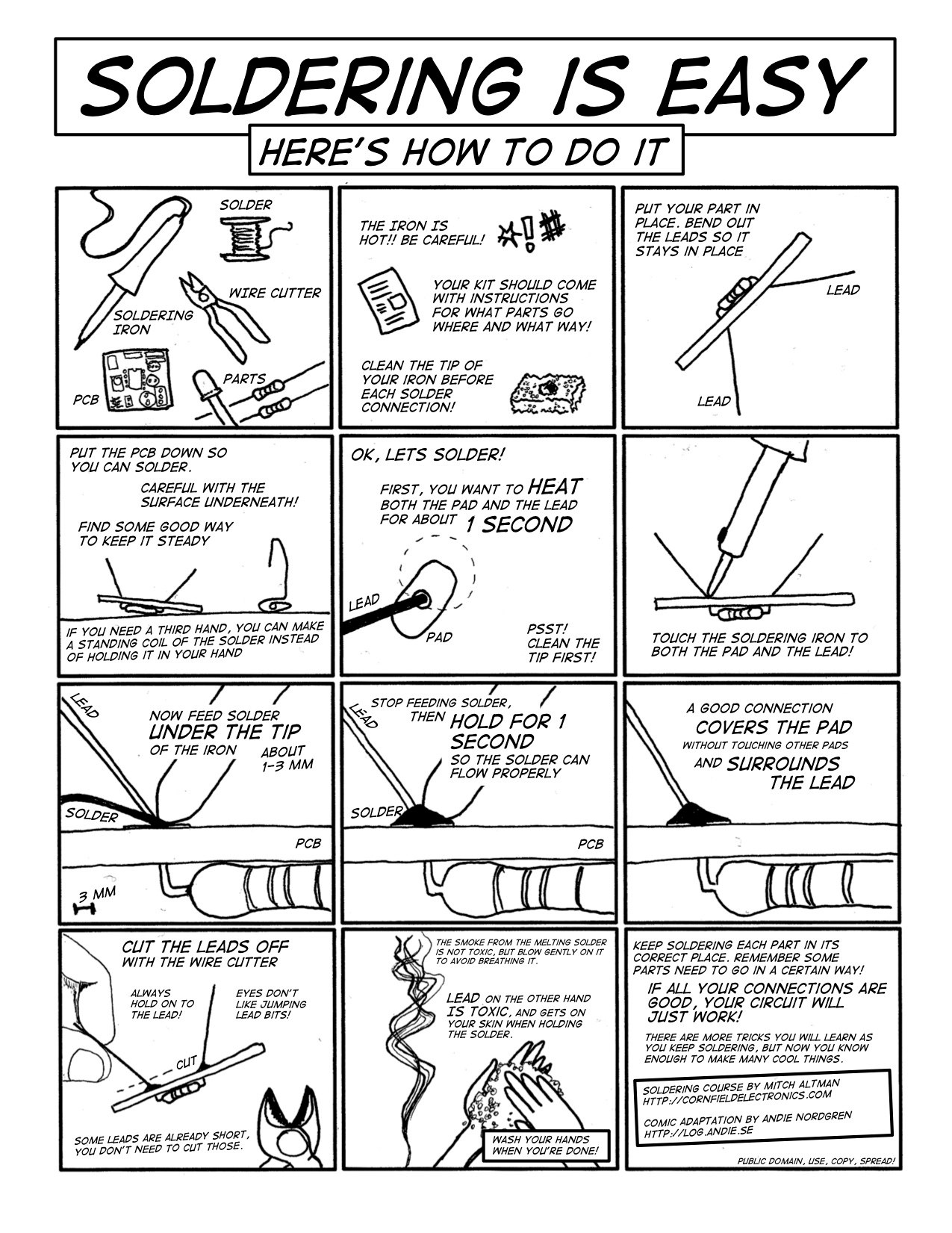
Soldering is Easy is a one page cartoon guide to soldering by Andie Nordgren, and is included below. Click the image to view the entire guide. If you’d like to read a lot more about soldering, or watch some videos, visit SparkFun Electronics, NASA , or Curious Inventor.
Step 1: Part identification
Open up the container of parts, and make sure you have all the parts listed below. It may be useful to check them off a printed copy of the instructions, or lay them out as seen in the photo.
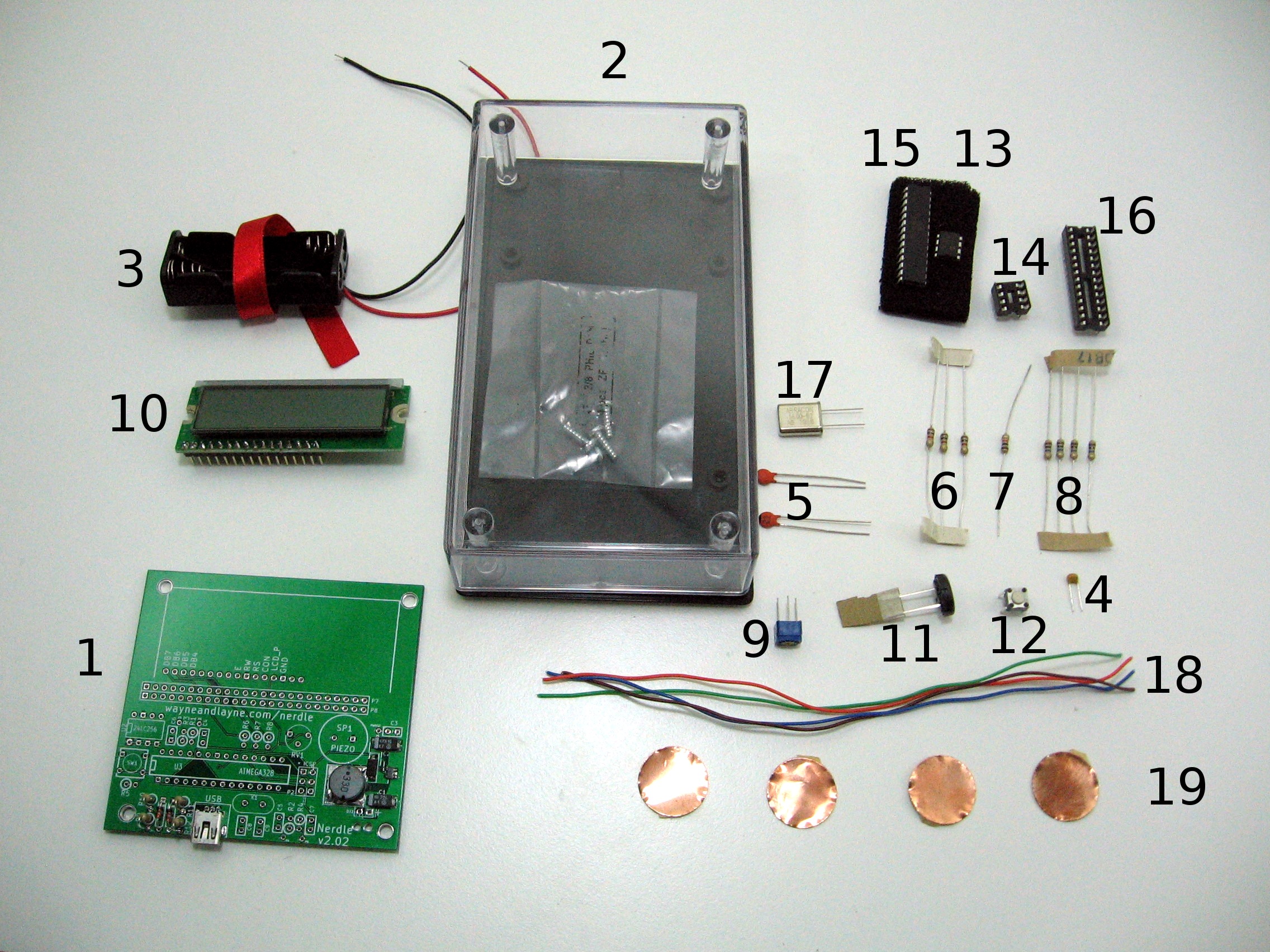
Click to enlarge
You can tell the resistors apart by the colored bands.
Because some of the board is pre-soldered, not all the part numbers are in order.
Make sure you have all the parts before proceding to the next step.
- (1) Nerdle printed circuit board
- (1) Nerdle case
- (1) 2 AAA Battery Holder
- (1) 0.1uF ceramic capacitor
- (2) 22pF ceramic capacitors
- (3) 1K resistors (brown, black, red)
- (1) 10K resistor (brown, black, orange)
- (4) 10M resistors (brown, black, blue)
- (1) 10K potentiometer
- (1) Character LCD display
- (1) Piezo speaker
- (1) Push button
- (1) 8 pin EEPROM chip
- (1) 8 pin chip socket
- (1) 28 pin Atmega328 microcontroller
- (1) 28 pin chip socket
- (1) 16 MHz crystal
- (4) wires
- (4) copper pads
Step 2: Power Supply
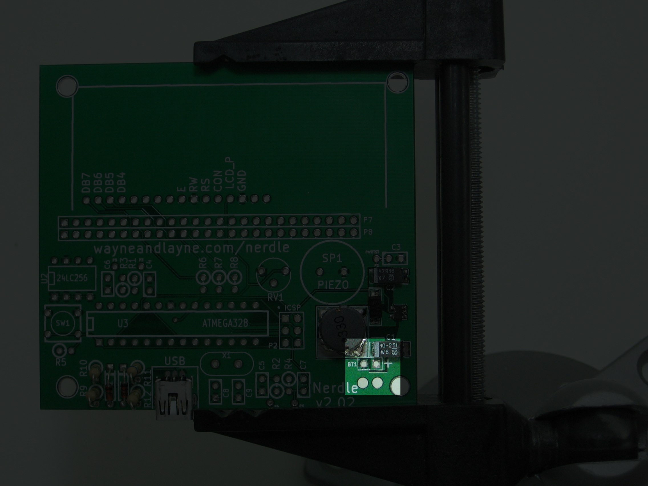
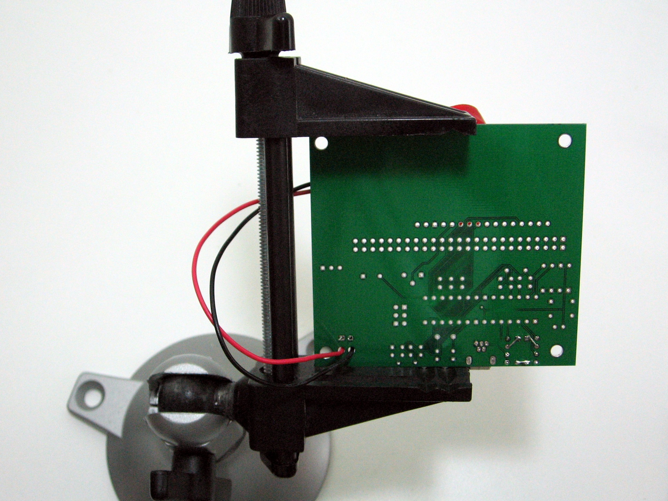
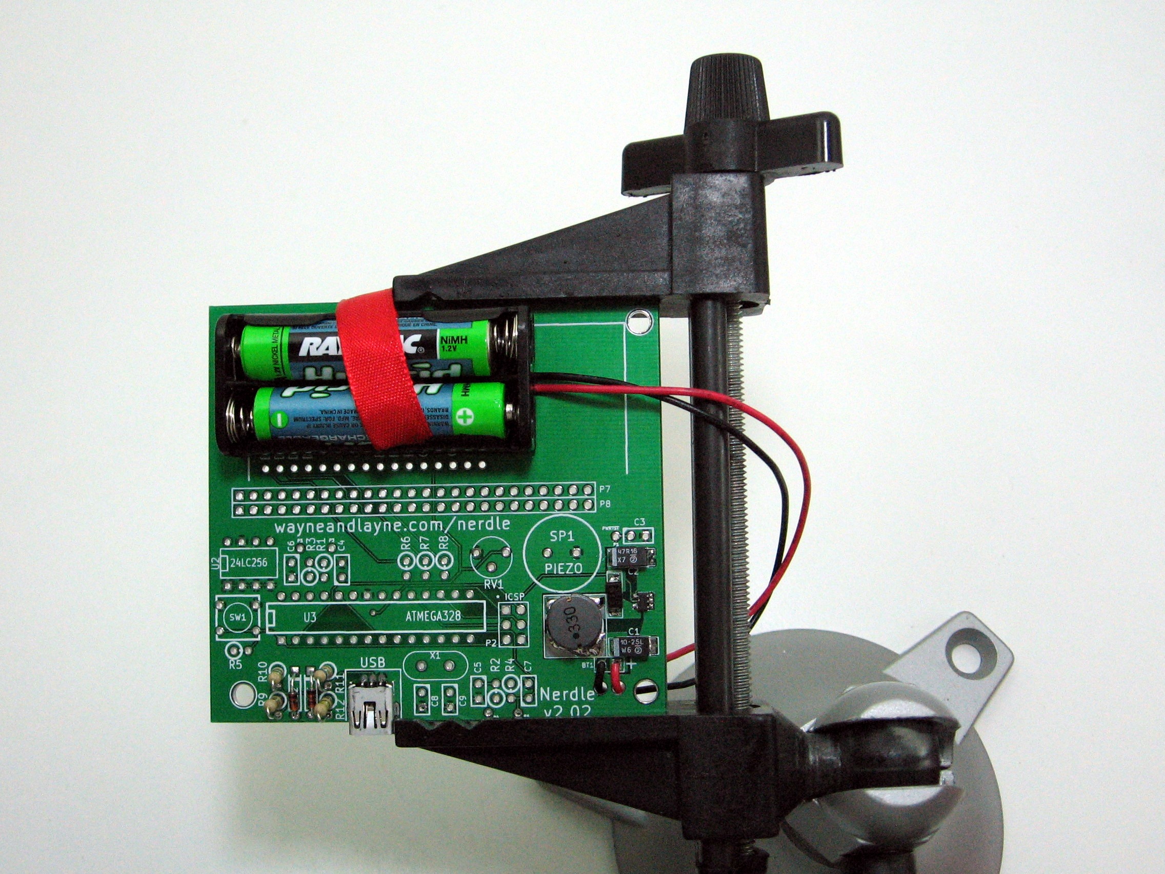
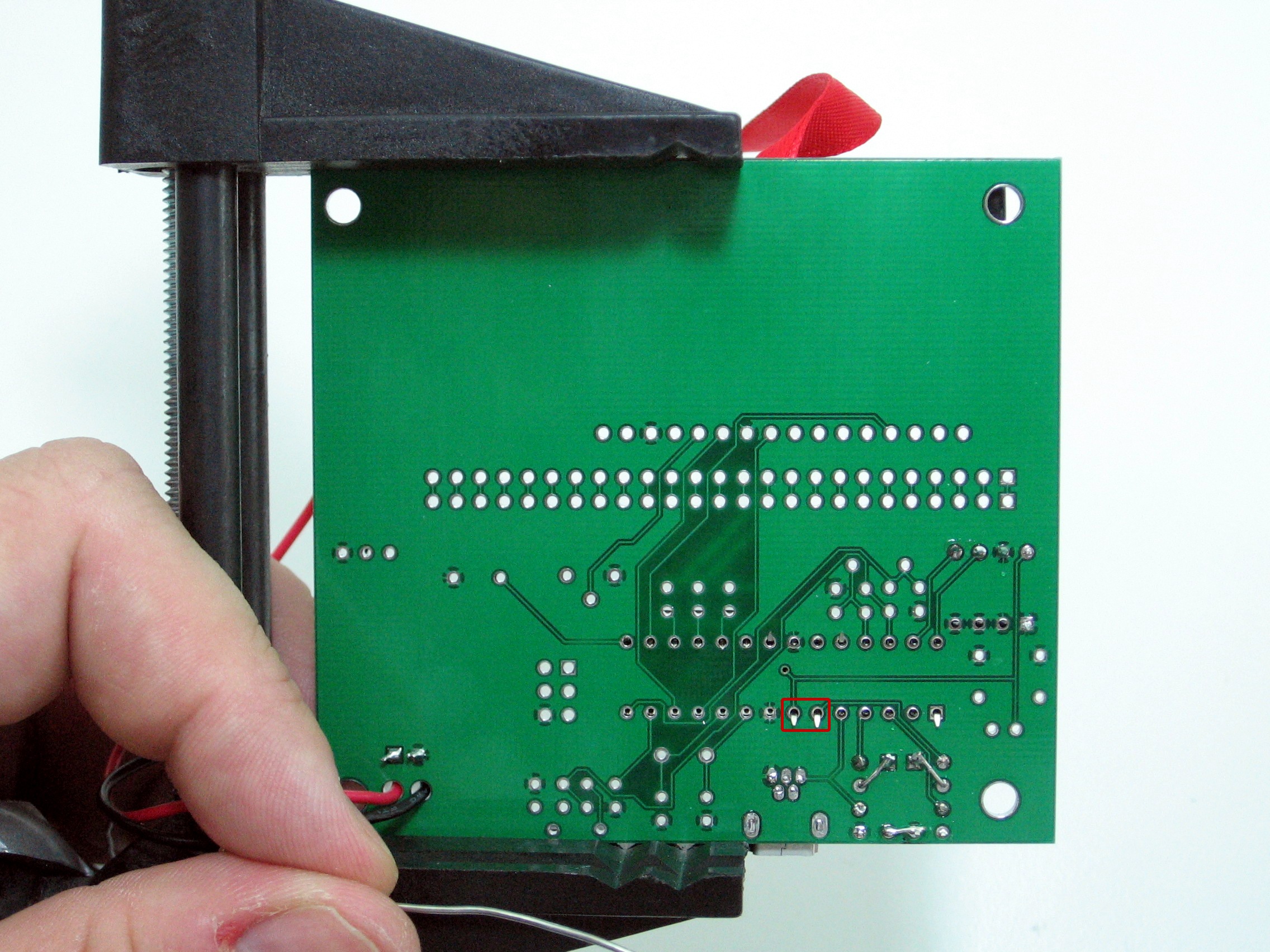
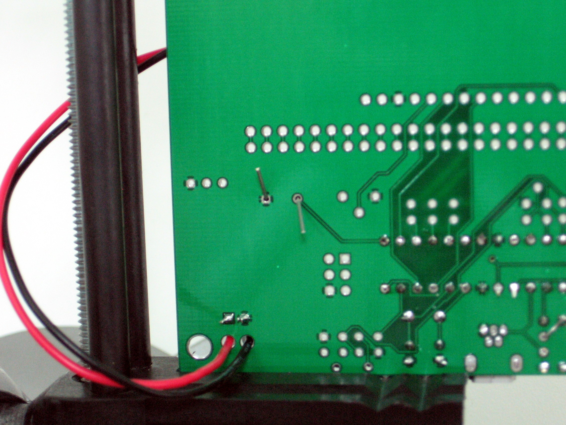
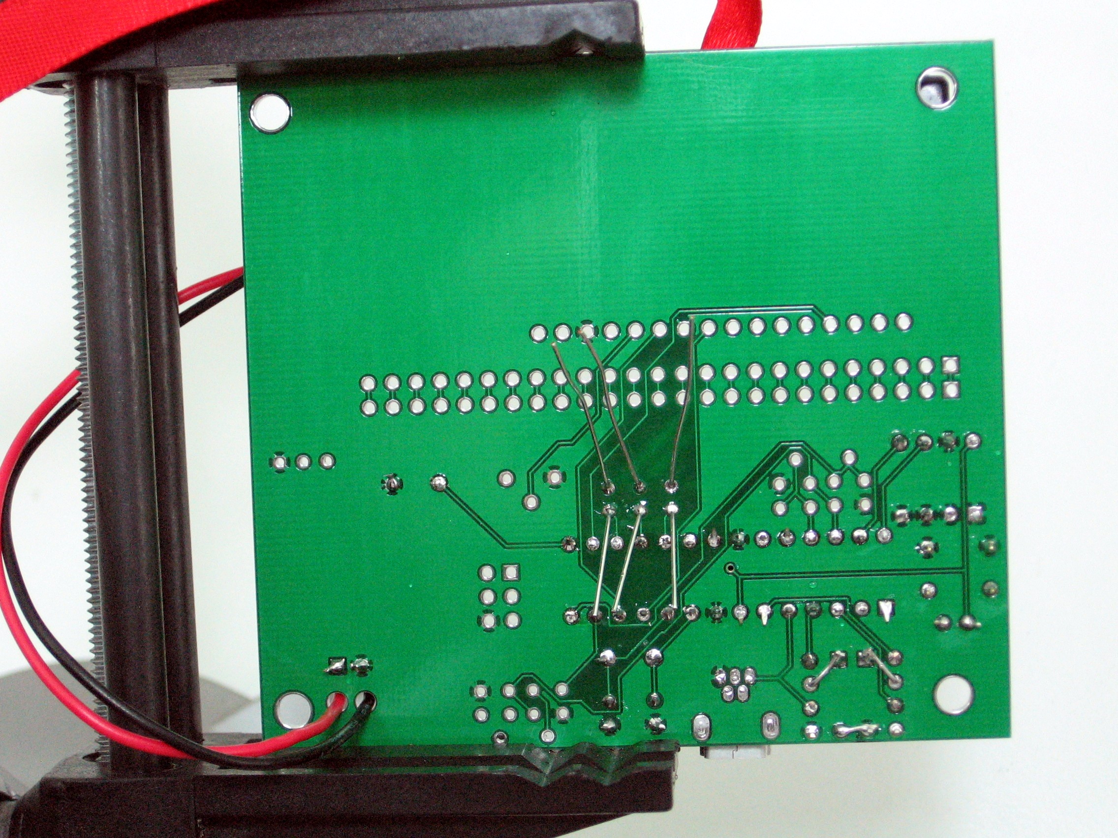
The next step is to verify that the presoldered power supply functions correctly. To do this, we have to first attach the battery holder to the PCB. This component is polarized, which means that it matters which wire goes into which hole. In the bottom right corner, there is a designator of BT1. Next to one of these holes, there is a +. The red wire goes to there, and the black wire goes to the other hole. There are two strain relief holes. First, put the wires through the respective holes from underneath the PCB, and then poke the wires through their holes from the top. Now, flip the board over, and solder the two wires in.
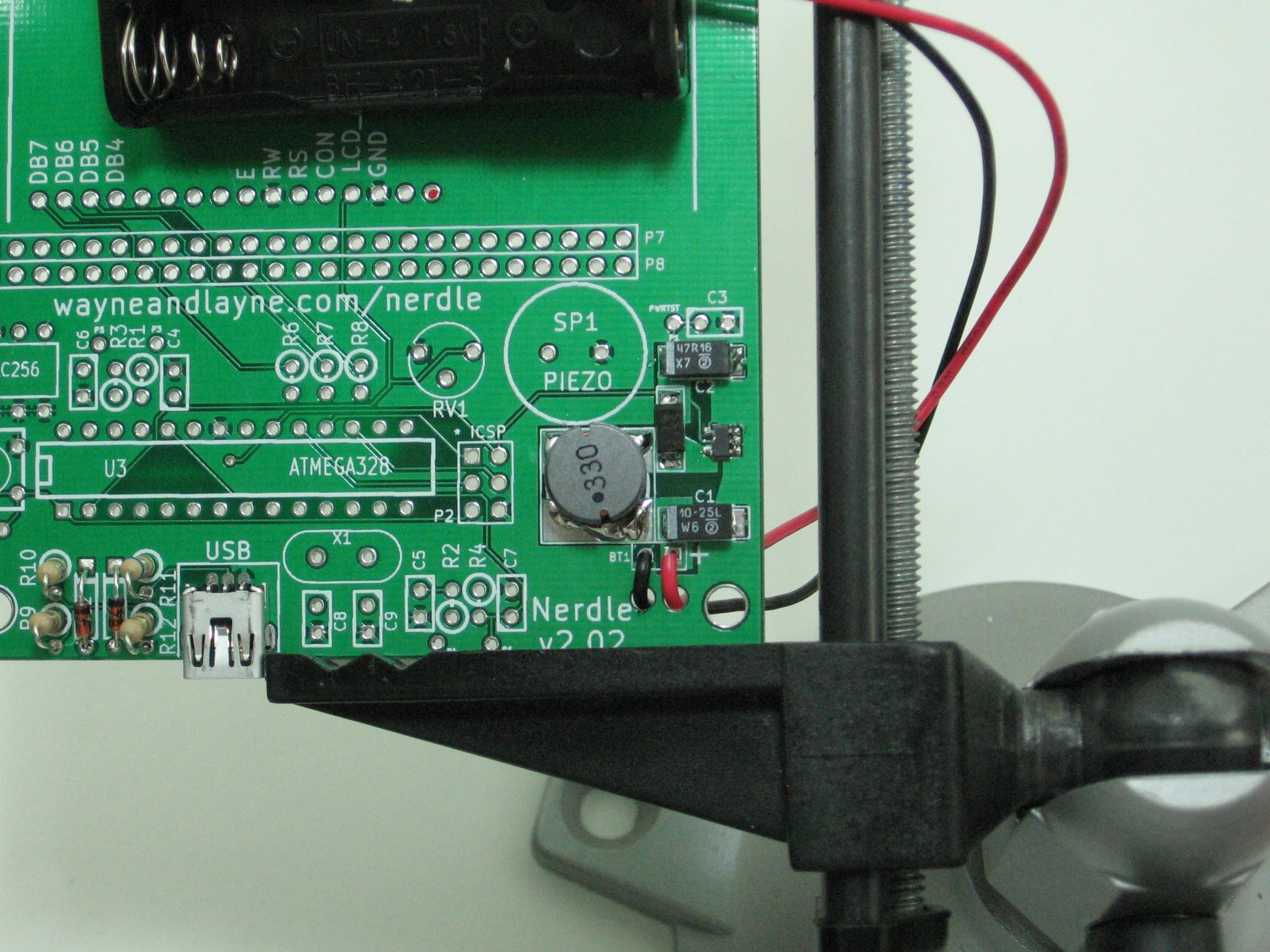
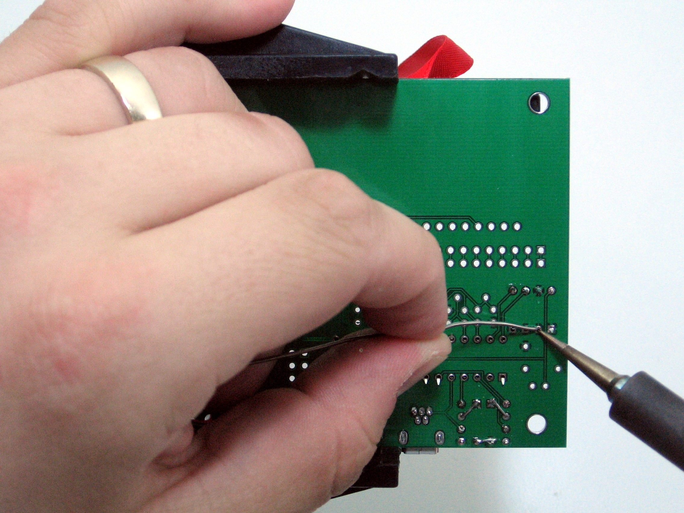
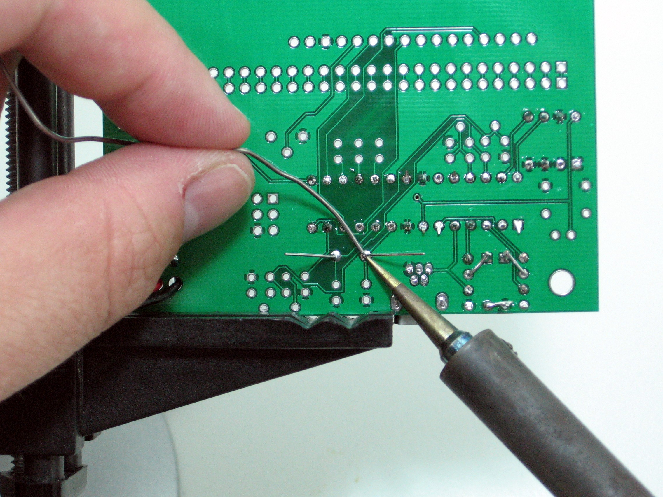
Use your soldering iron to heat up the wire sticking through and the ring around the hole at the same time. Push a little bit of solder on the ring. The solder should melt and flow around the hole. If you’re having trouble, make sure the tip of your iron is tinned and shiny. Remember to heat up both the wire and pad, and you don’t need to apply a lot of solder. Don’t try to use the iron like a paintbrush. You can review the soldering comic below.
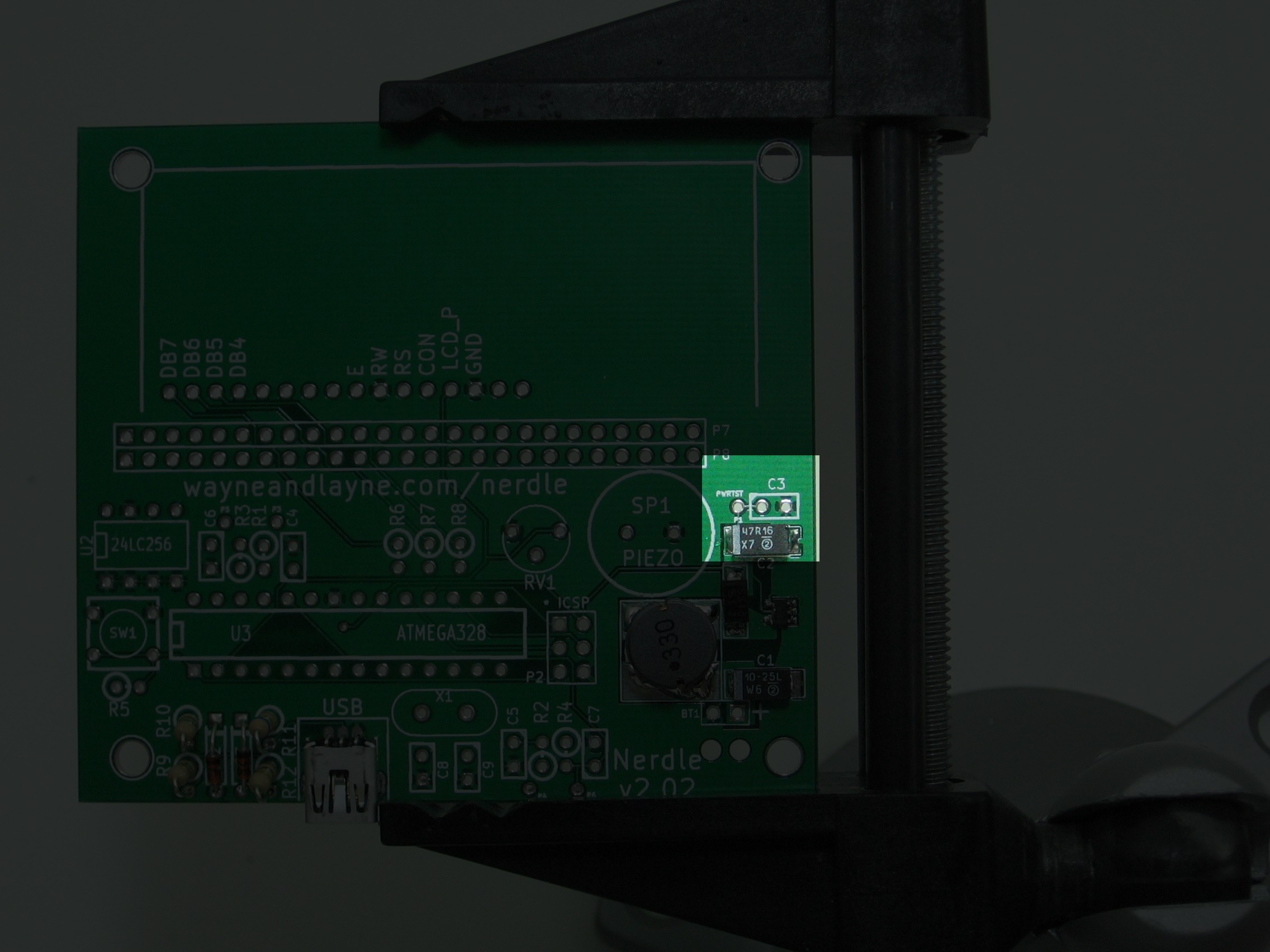
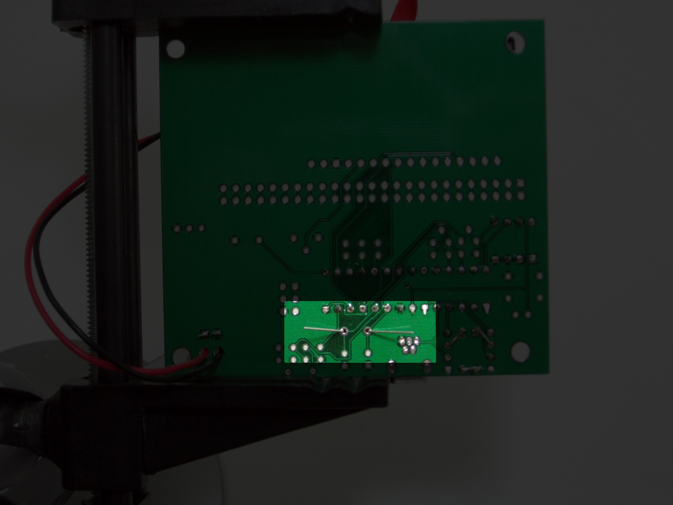
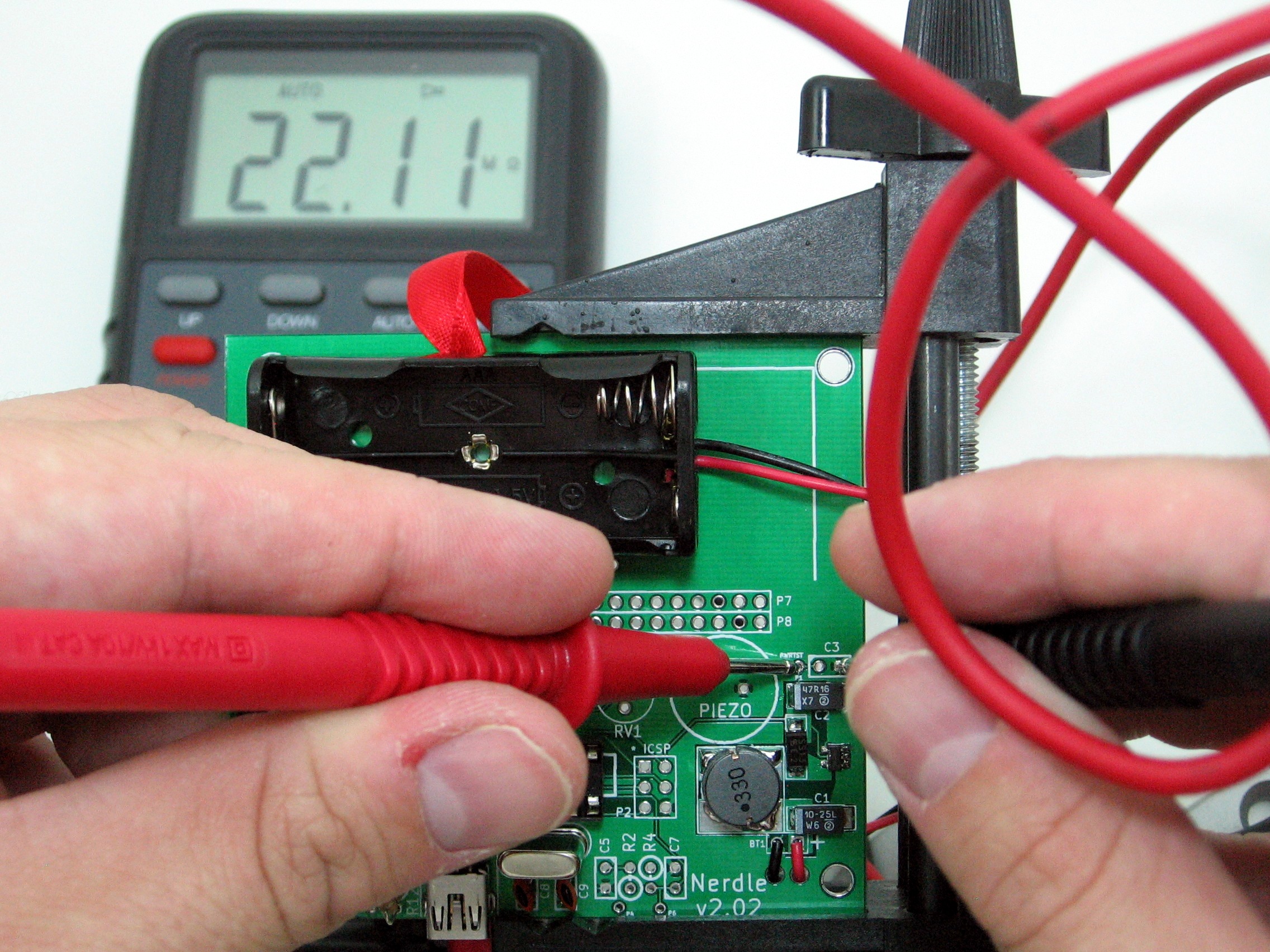
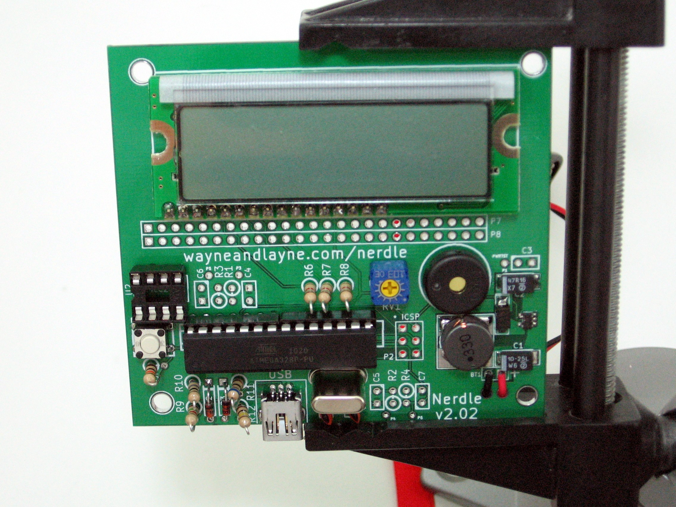
Be very careful, as a short here can be catastrophic. To check for problems, use a multimeter to measure the resistance between the two indicated solder points. The resistance should be very high (in the megaohm range) or else display an error. A low value means there is a short, and this needs to be cleaned up. In the picture below, our multimeter is measuring 22.11 megaohms, a very large value, meaning there are no shorts in the circuit.

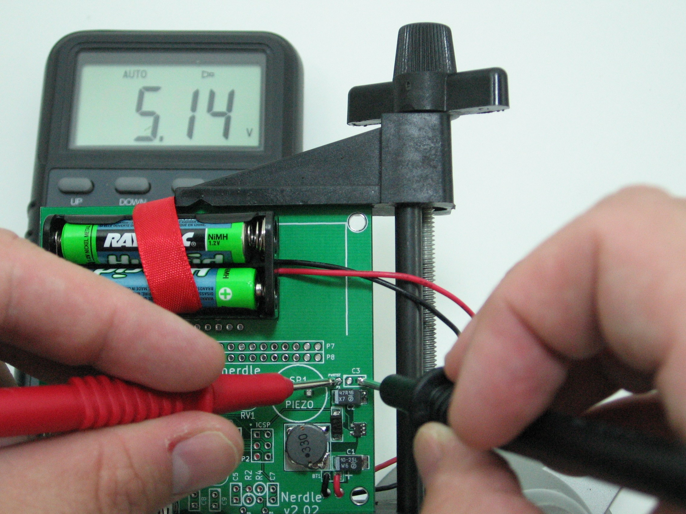
If the resistance is high (or so high it displays an error), insert the batteries. The flat end of the battery goes on the spring part of the holder. There is also a diagram on the inside of the battery holder. Use the multimeter to measure the DC voltage between the same two test points. It should be around 5 volts. When we tried it, our multimeter displayed 5.14 Volts, a good value to see. The voltage shouldn’t exceed 5.2 volts or be less than 4.8 volts.
Before you continue with the next step, remember to remove the batteries.
Step 3: Sockets
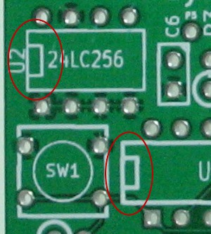
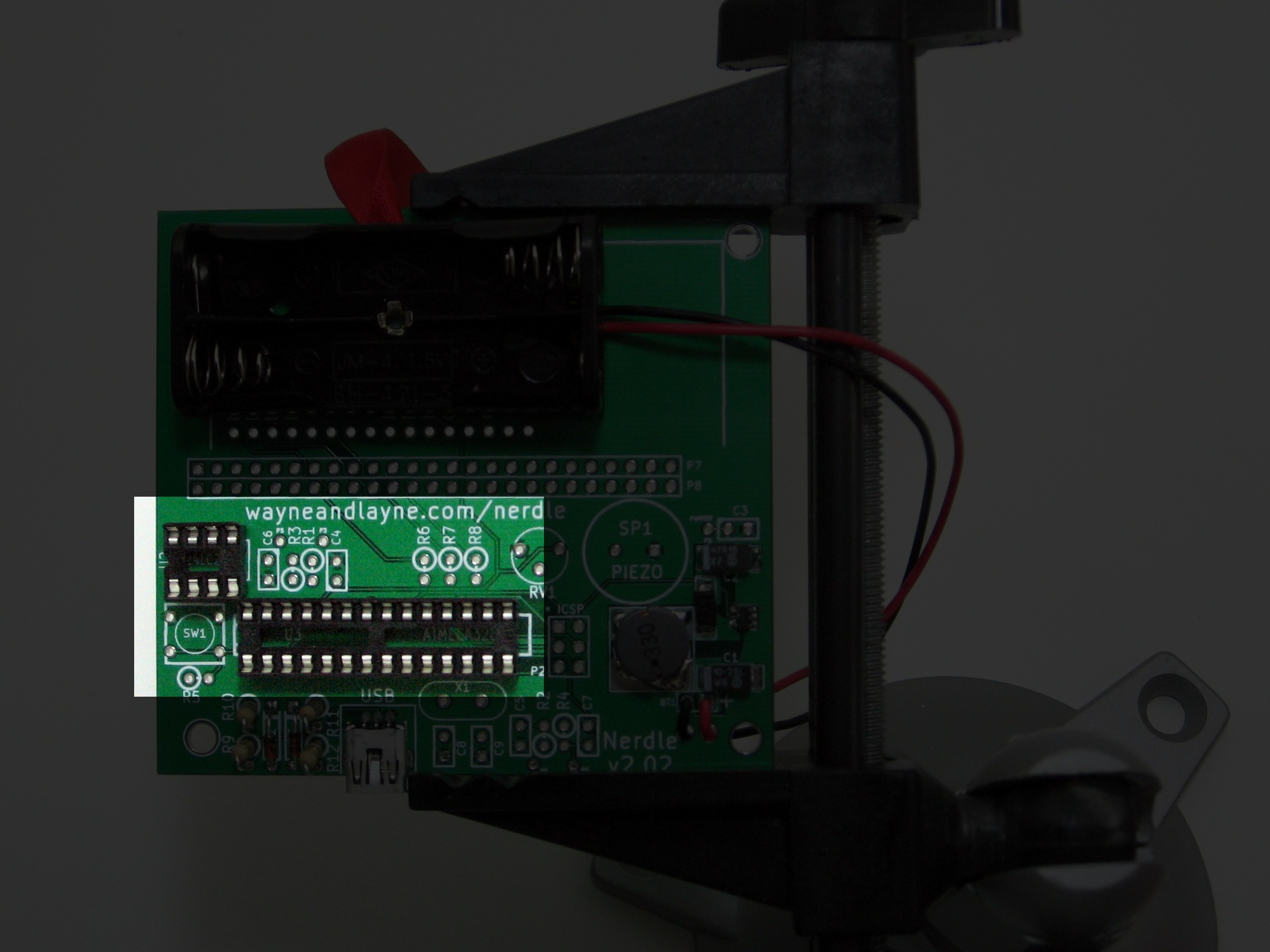
The next step is to solder the sockets to the board. These hold the chips to the PCB, and allow us to remove the chip if needed. Insert the sockets into their proper areas on the board, labeled U2 and U3. There is a notch in one end of each socket that should line up with the notch in the drawing on the PCB.
It usually helps to bend one of the legs to keep the socket in place while soldering. Take care to ensure that the socket is flush against the PCB while soldering, because it can be difficult to insert a chip into a crooked socket. Flip the board over, solder one leg, and then flip the board back. If the socket isn’t pressed up against the board, reheat the connection while pressing the socket to the board. Finish soldering the rest of the connections. Do the same for the other socket.
There are a lot of connections here! If the solder starts to act like putty, or the soldering starts to get more difficult, your iron is likely too cold. Take a little break and let the iron heat back up.
When you’re all finished, be sure to visually check for shorts between pins.
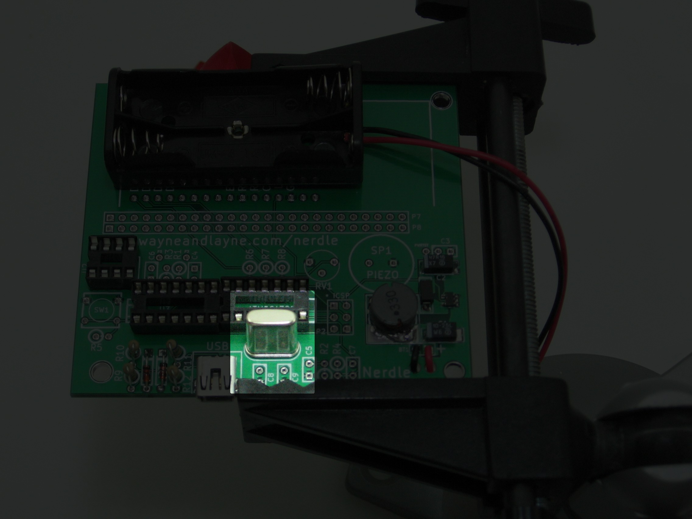
Step 4: Crystal and Crystal Capacitors
Put the crystal into the area marked X1. It can go either way. Bend the legs a little, and flip the board over.
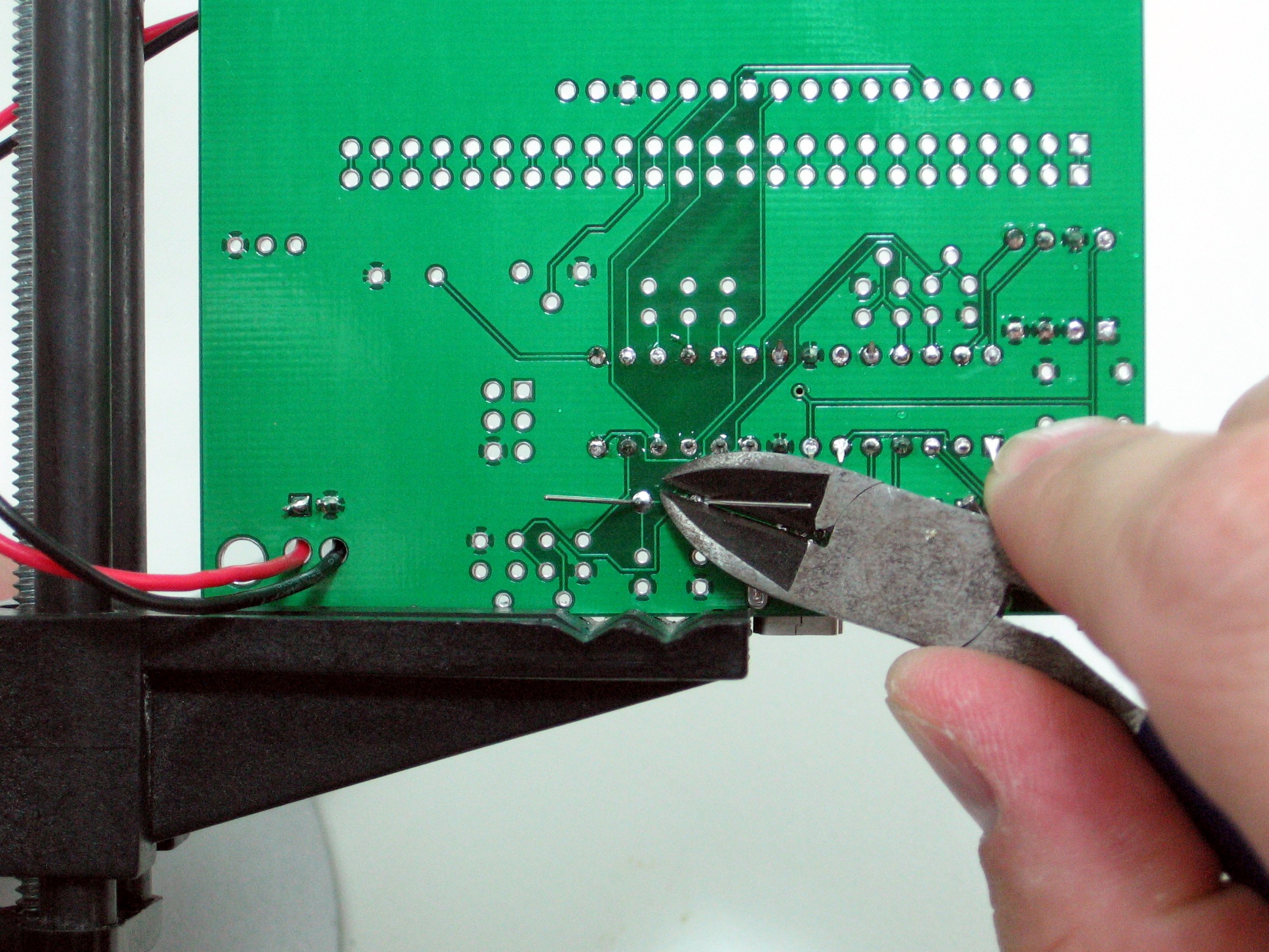
Solder the two connections and use the diagonal cutters to trim the legs. Don’t leave too much wire behind, but don’t cut into the solder blob.
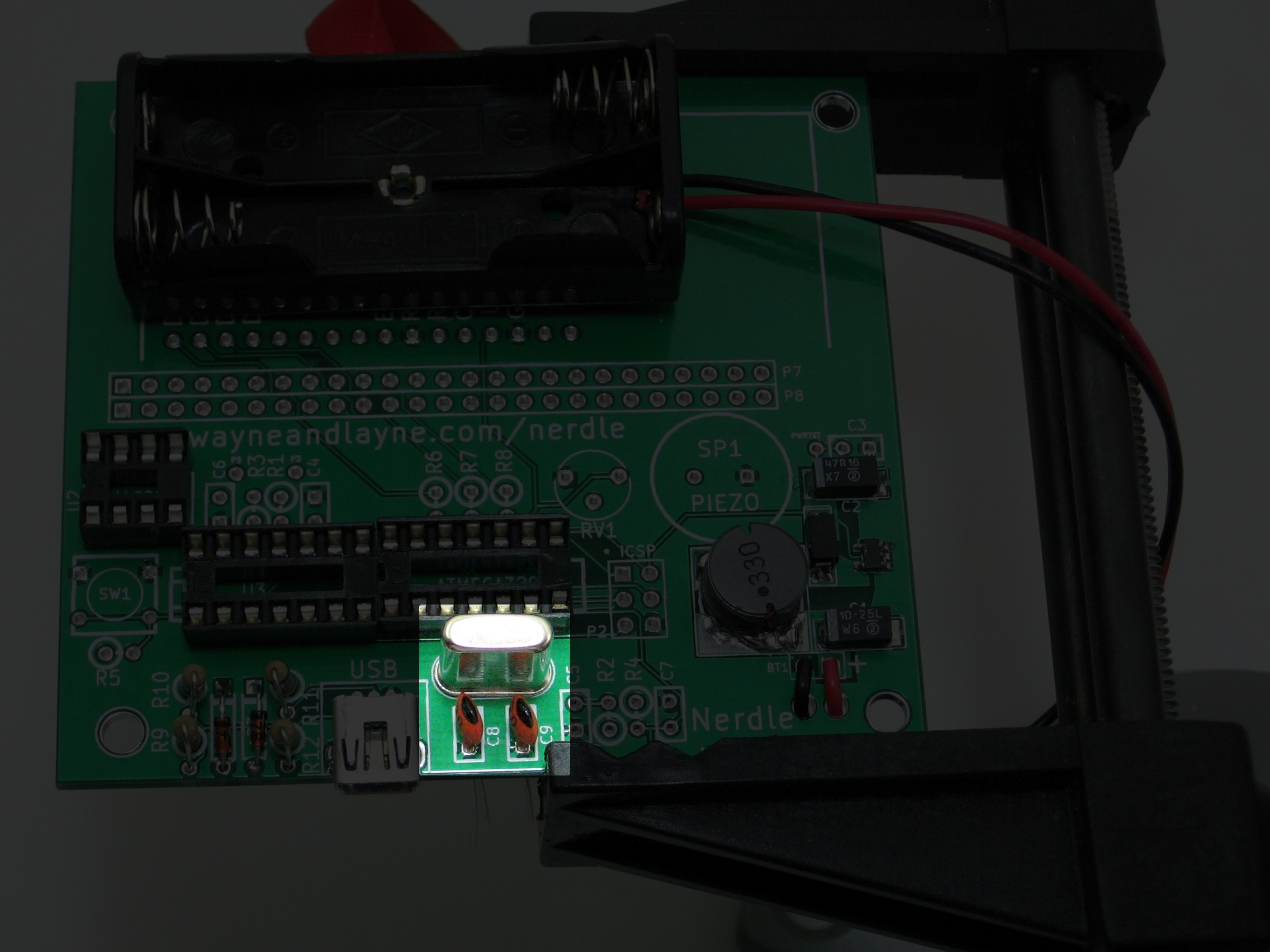
Next, add the crystal capacitors, C8 and C9. These can go in either way as well. Flip the board over, solder their connections, and trim the leads.
Before proceeding onto the next step, check the resistance between the power and ground again using a multimeter set to measure resistance. The value should be in the megaohm range, or an error because the resistance is too large. If there is a low value, there is a short in your solder joints–double check them!
Step 5: Reset Button
Next, insert the reset button SW1 into the printed circuit board. It can be tricky to fit in, so feel free to use a pliers to flatten the leads like the bottom buttons in the picture below.
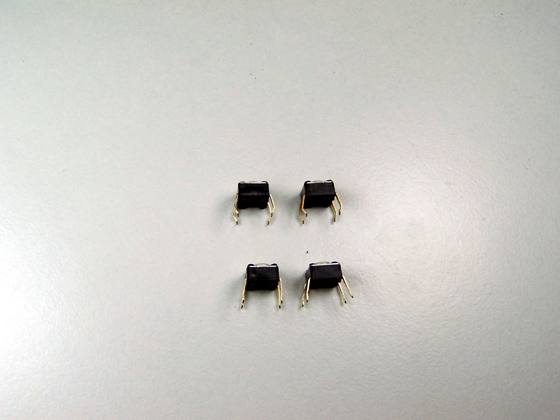
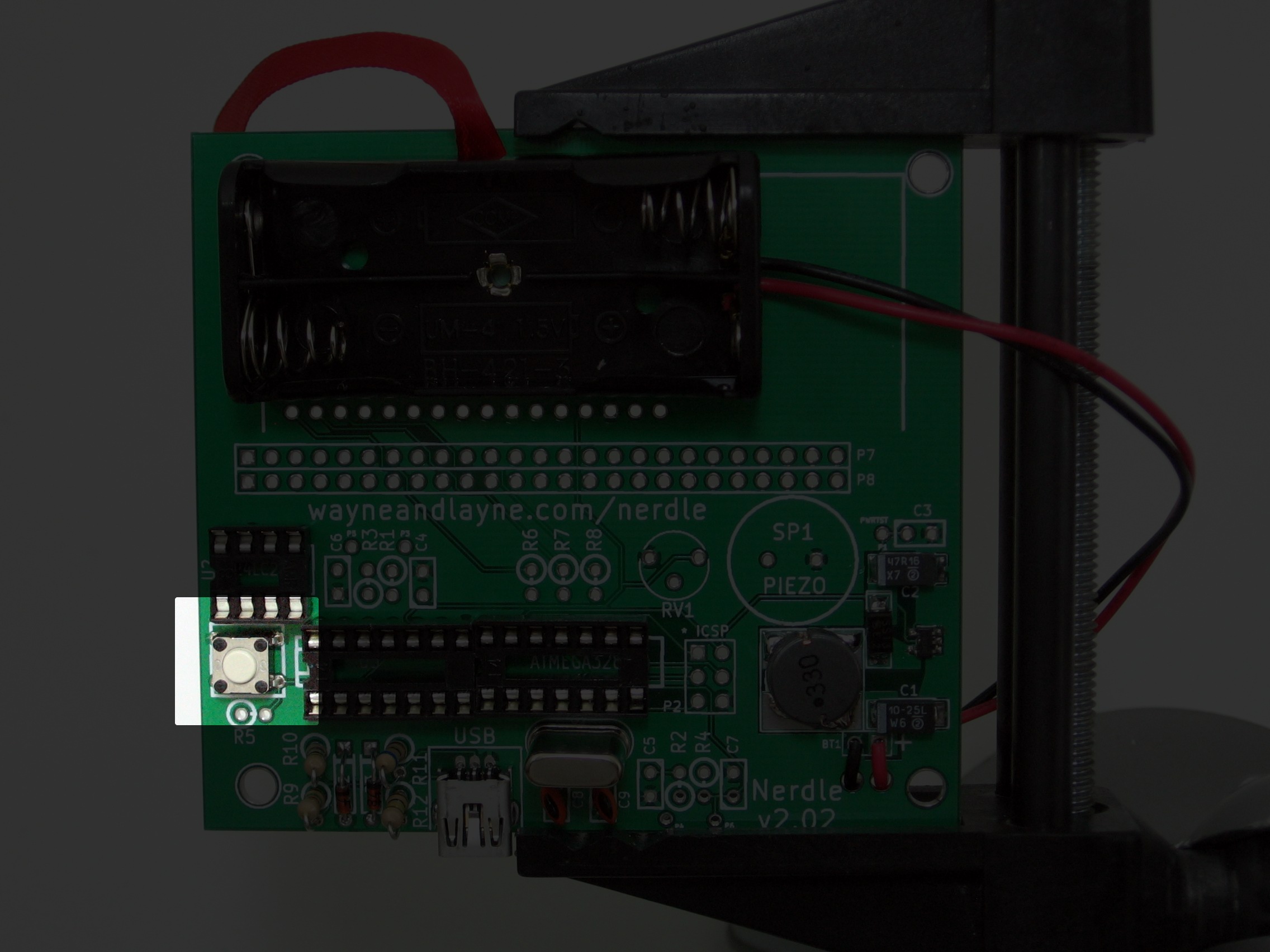
We want the plastic base to be pressed right up against the printed circuit board. Solder the four connection points.
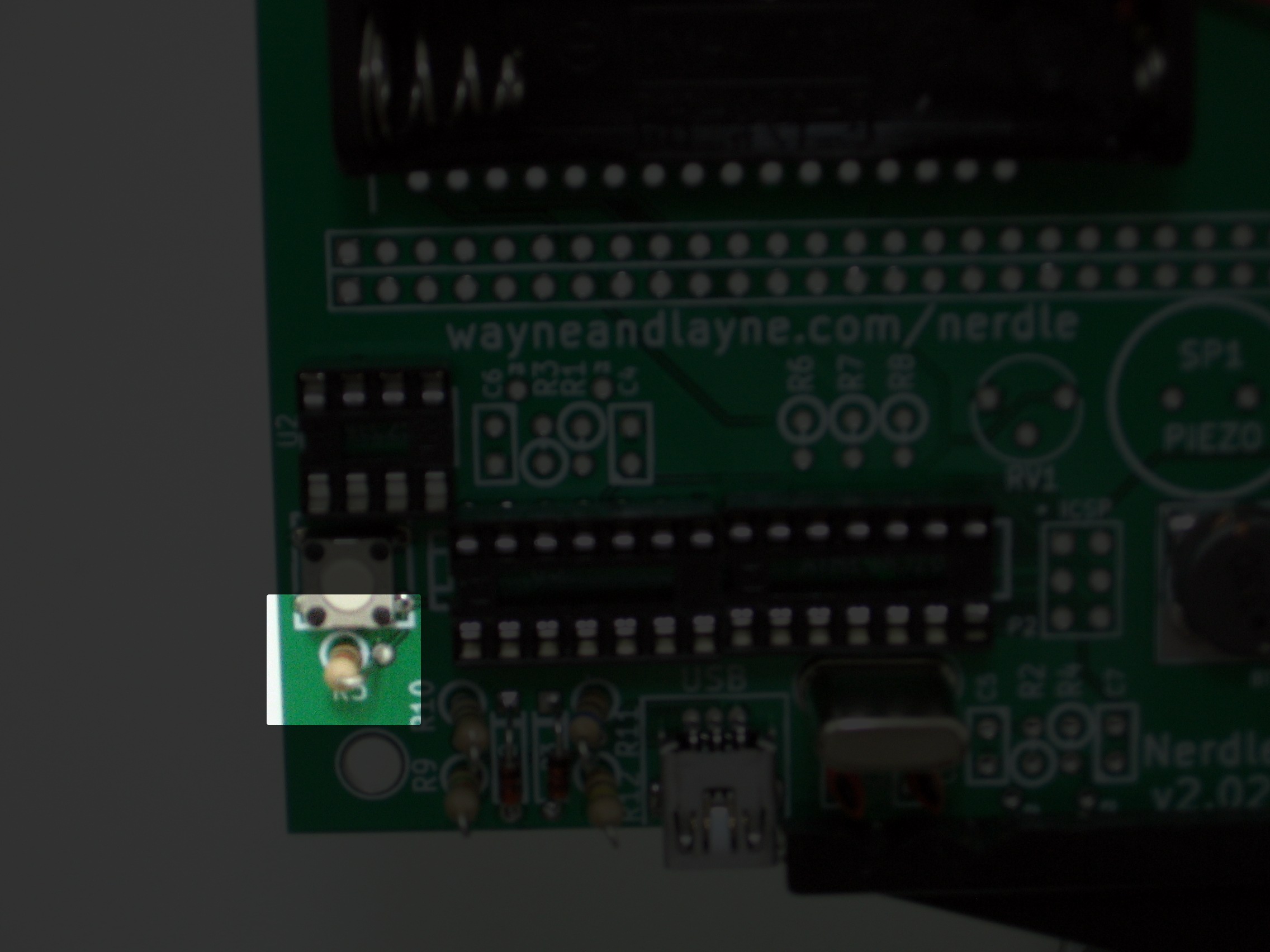
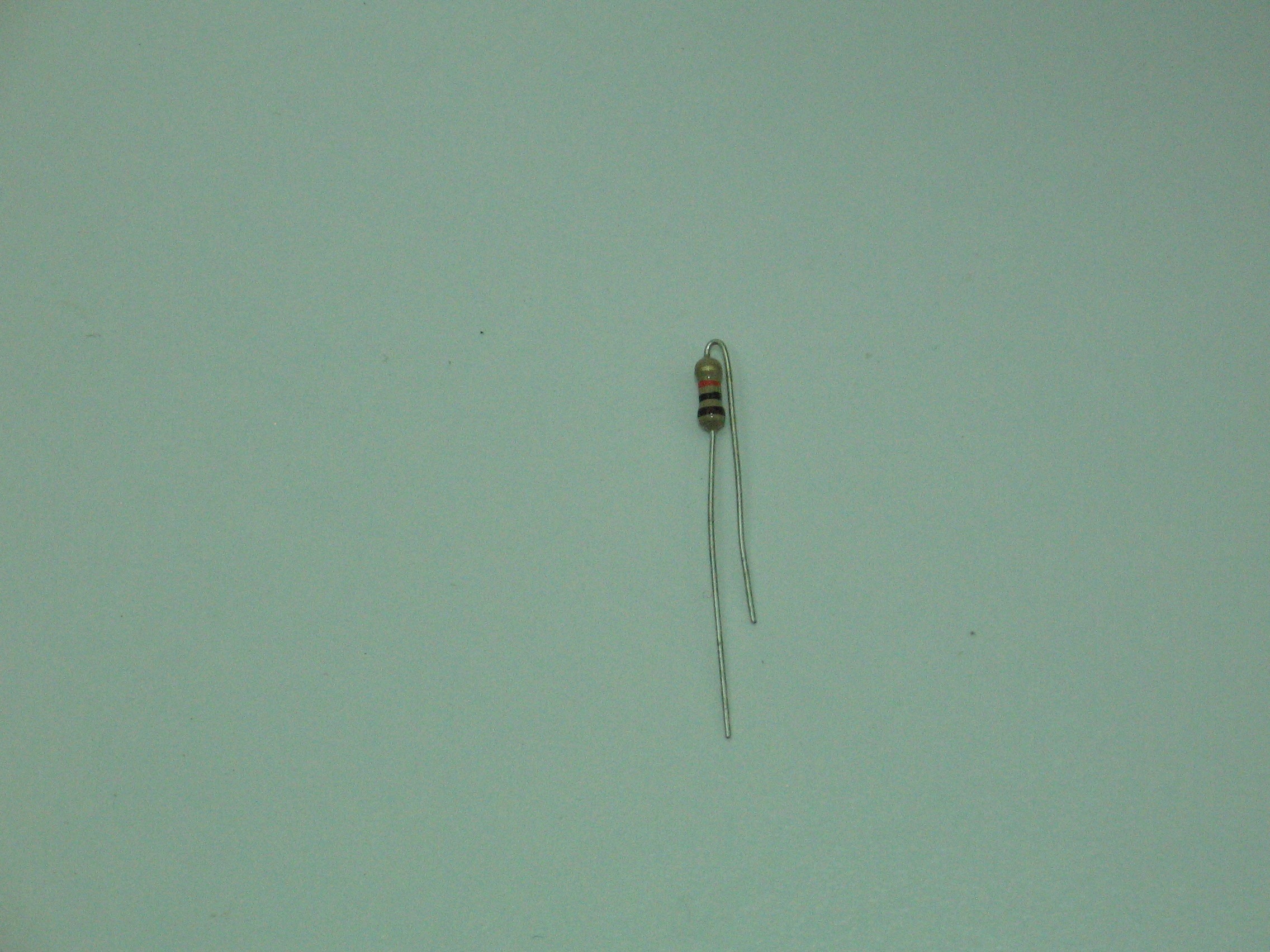
Step 6: The first resistor
Take the 10k resistor, labeled with brown-black-orange, and bend one of the legs all the way back towards the other end. Insert it into the board where it is marked R5. The white circle indicates the body of the resistor should be on that side, and the top lead should go into the other hole. Solder the two connections, and trim the legs.
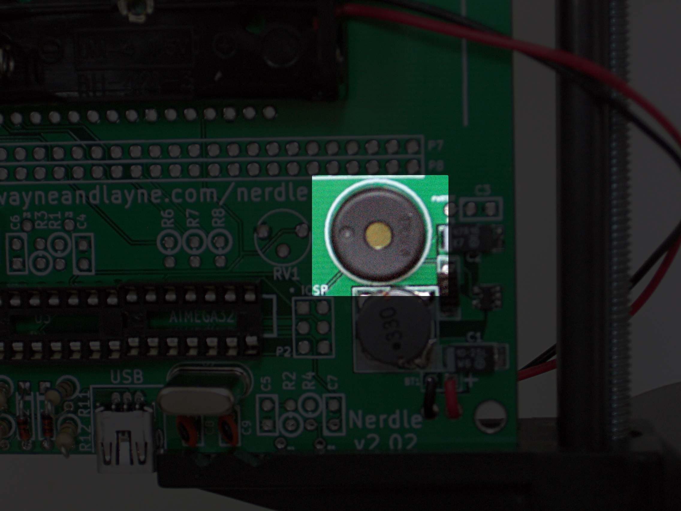
Step 7: Piezo Speaker
Insert speaker SP1 into the marked holes on the board. This part can also go in either way. Carefully bend the legs a little and flip the board over. Solder the connections and trim the legs.
It’s time to check our work before proceeding onto the next step. Check the resistance between the power and ground using the same test points as before. The resistance should still be in the megaohm range. If it isn’t, there is likely a short between some solder joints. Check your work and try again.
Step 8: Adding the microcontroller
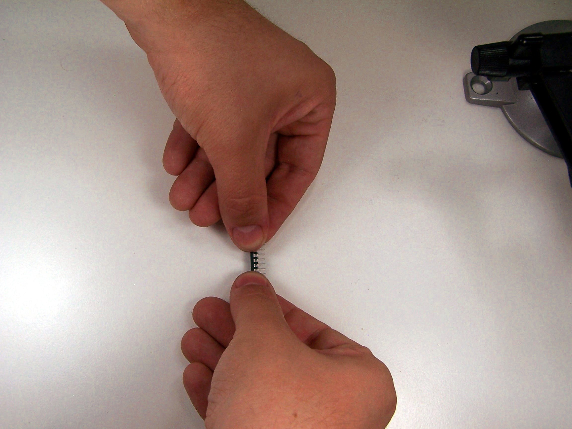
The microcontroller only goes in one way. There is a notch on one of the ends. This matches the notch on the white diagram on the board. Insert the microcontroller carefully. If the legs are too spread apart, they can be fixed using a simple technique: You can slightly but uniformly bend the legs by pressing the chip against the table as shown in the photo below.
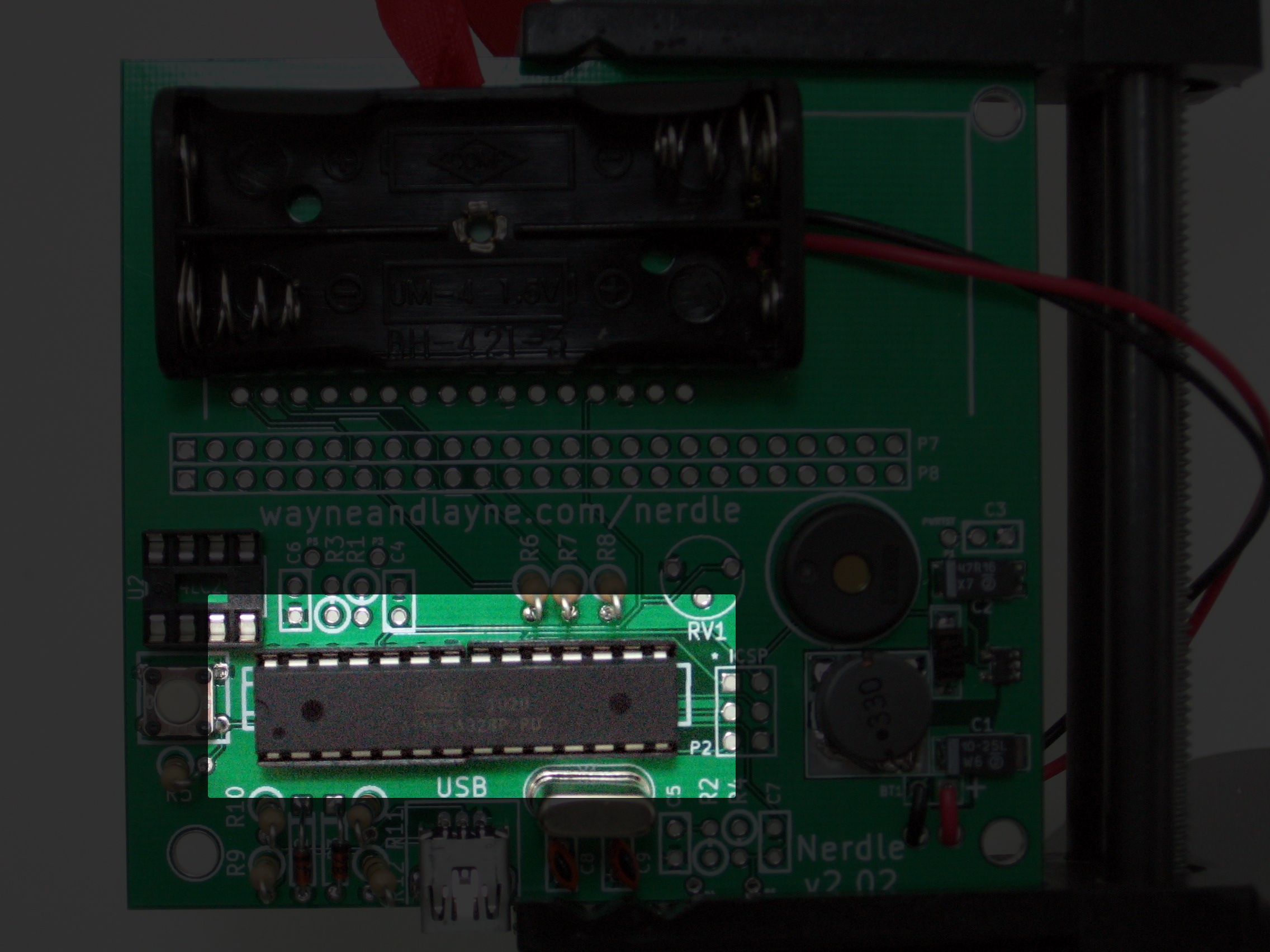
Insert the microcontroller all the way. Check the resistance: If it’s still high, add the batteries. You should hear a beep, indicating that the microcontroller is working! Take the batteries out. If you don’t hear a beep, remove the batteries and double check your work.
Step 9: More resistors
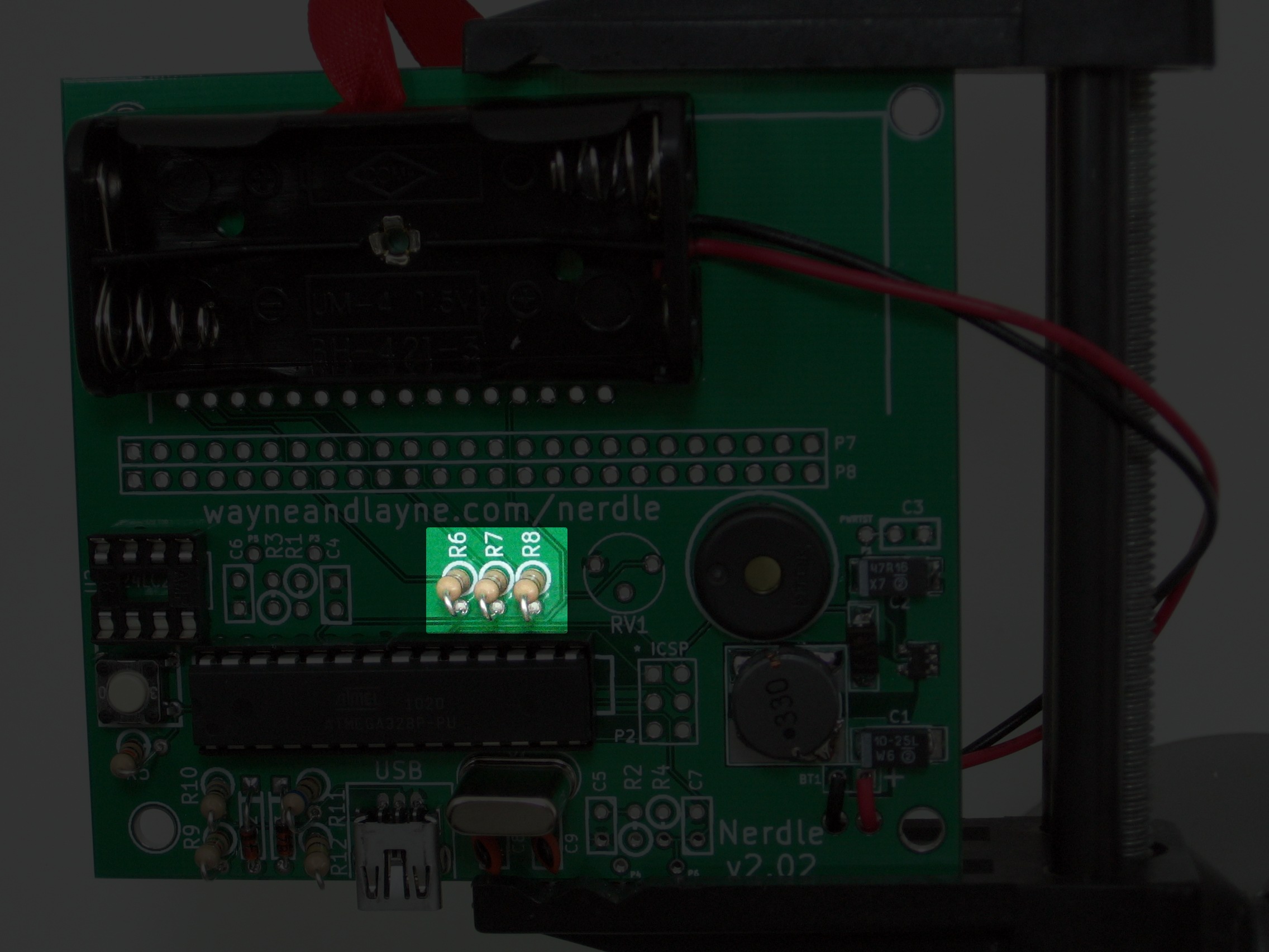
Place the 1k resistors, labeled with brown-black-red, into the resistor areas labeled R6, R7, R8. Use the white circle to guide their placement into the board. Solder each resistor and trim all the legs.
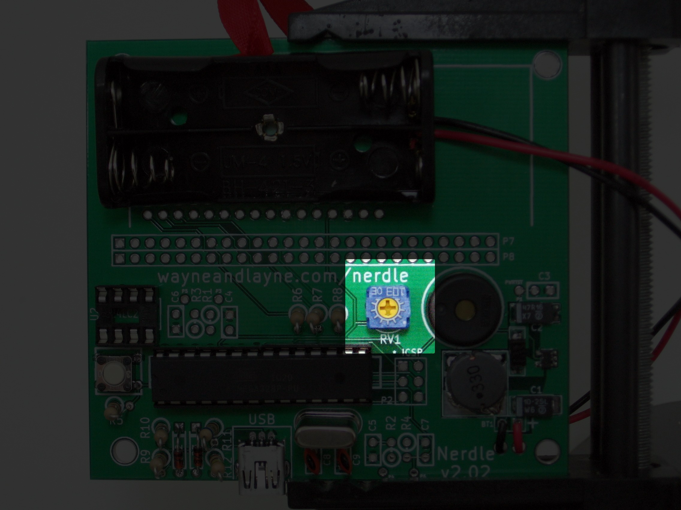
Step 10: Potentiometer
Next, put the potentiometer into the board, above the label RV1. The potentiometer looks like a little blue cube with a yellow dial on the top, and controls the contrast of the display. Solder and trim the legs.
Step 11: Display
Place the display into the top row of holes in the board. Solder a single pin, and then use a similar technique as used with the sockets to align the display while still only soldering the one pin. Solder the rest of the pins. When trimming these leads, you might need to use a fair amount of force–these pins are thick!
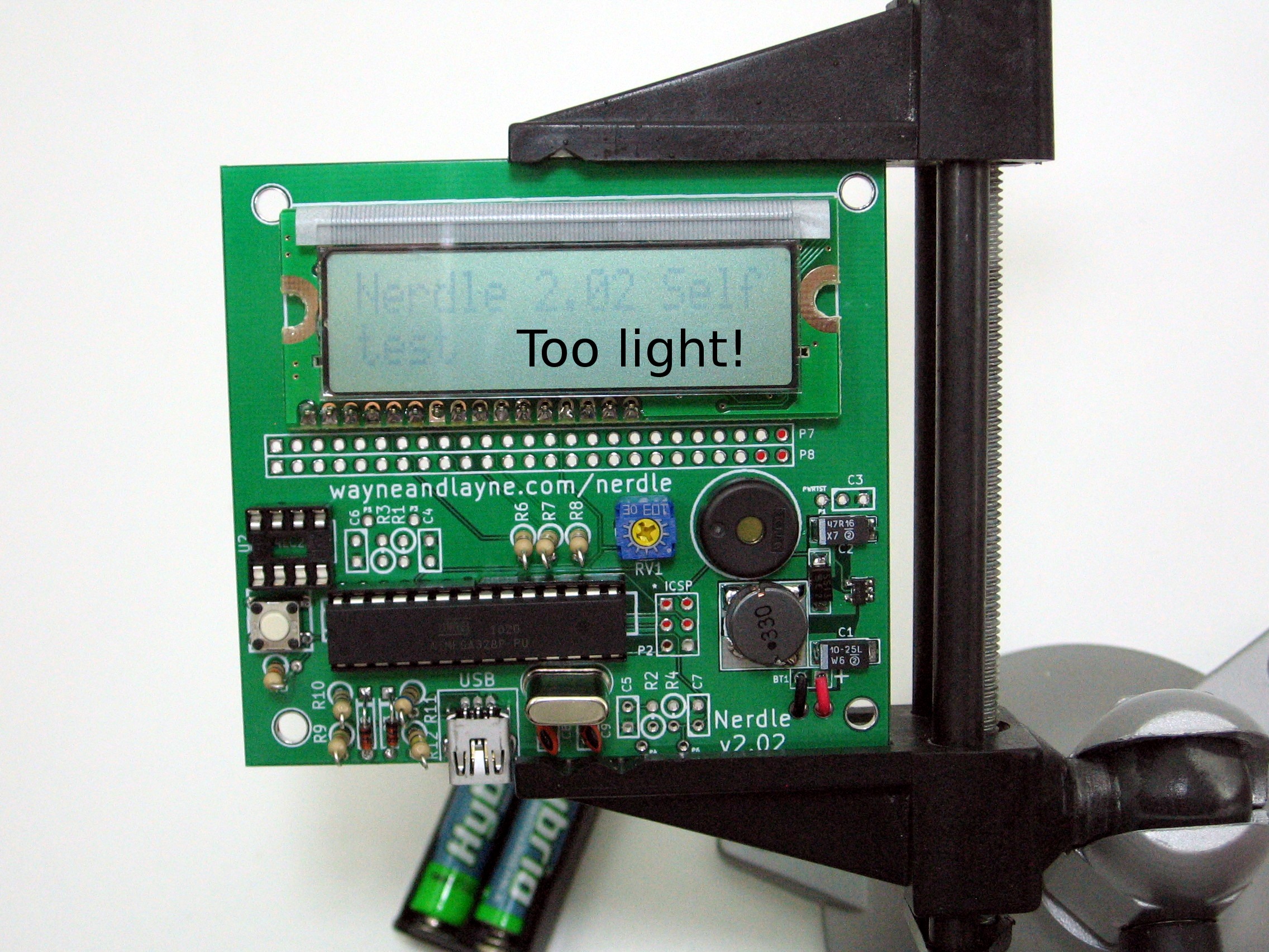
Step 12: Self-test
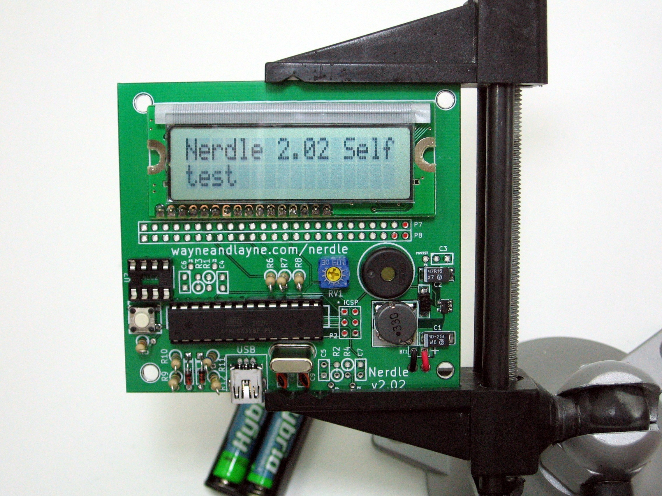
Check your work by checking the resistance again. It should still be in the megaohm range. If it is, add the batteries. You should hear a beep, then see “Nerdle v2.02 Self Test” on the display, and hear a second beep.
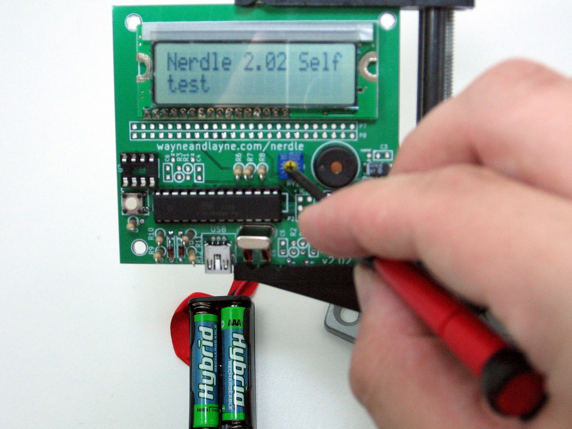
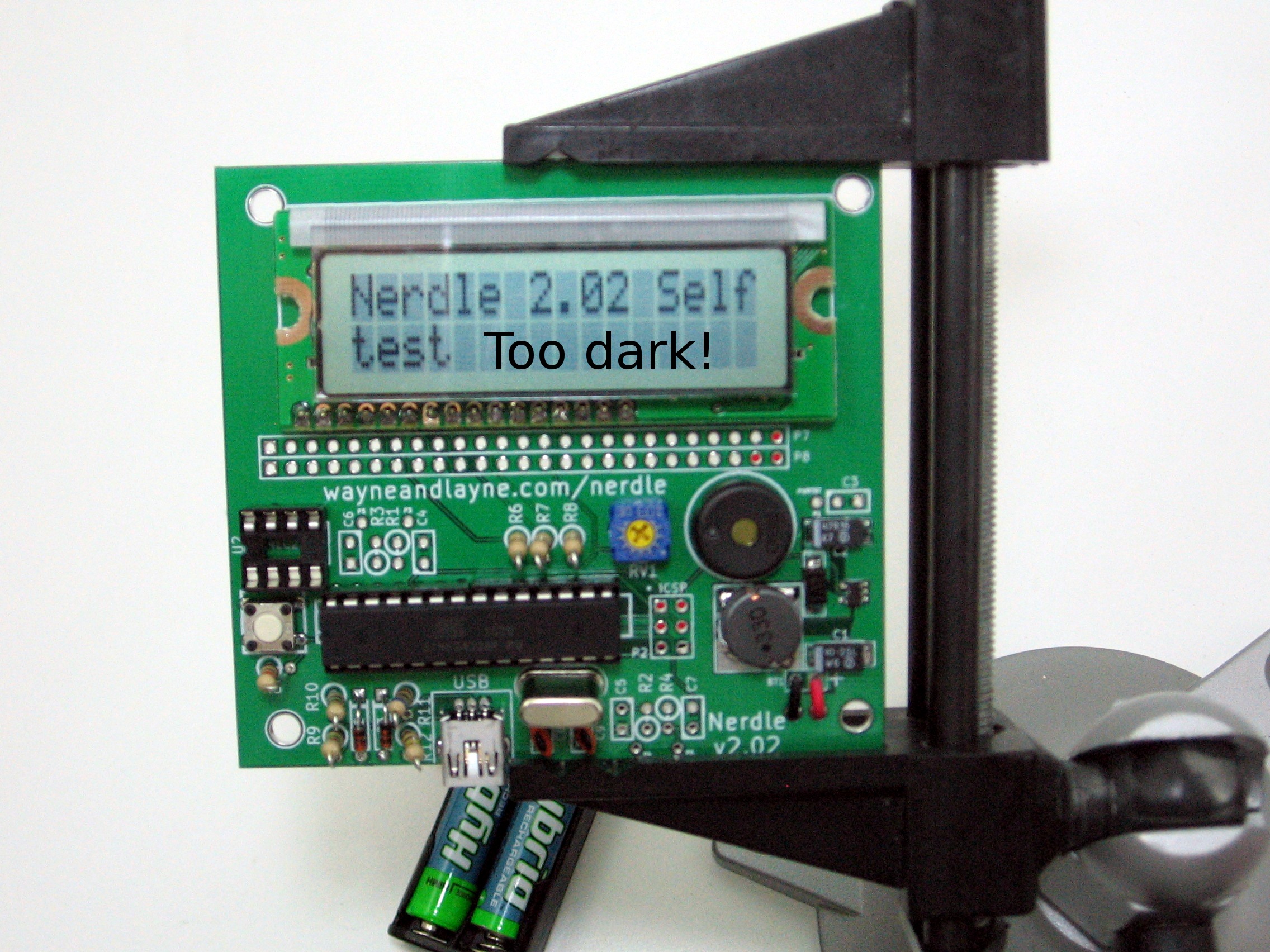
If you hear both beeps but don’t see anything, adjust the contrast potentiometer using a little screwdriver. If you don’t hear a second beep, double check your LCD connections!
Before you continue with the next step, remember to remove the batteries.
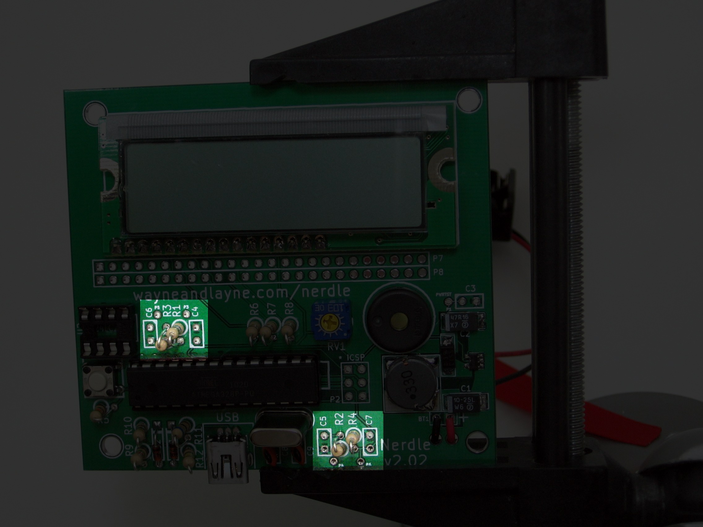
Step 13: Touch sensor resistors, power supply capacitor, chip
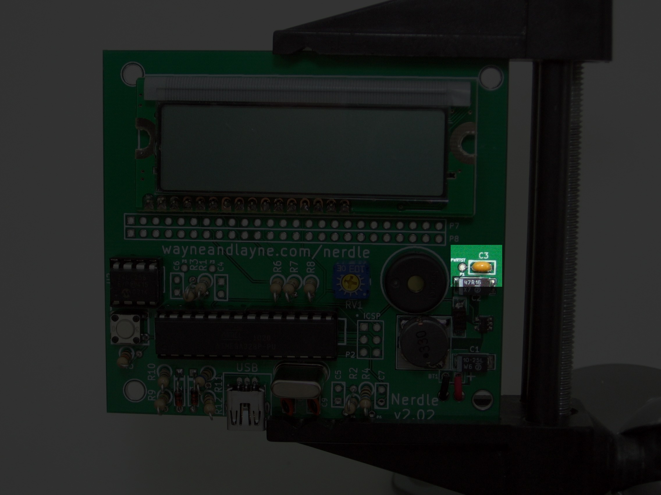
Add the remaining 10M resistors, there are four in total. They are labeled R1, R2, R3, R4. Use the white circles as a guide to their placement on the board. Solder them, and cut their legs. Make sure the metal parts of the resistors aren’t touching each other. Put the small capacitor in the area marked C3 by the test points. Solder, then trim the legs.
Put the 8 pin DIP chip into the socket. Line up the notch on the chip with the notch on the socket and with the drawn notch on the board.
Step 14: Case
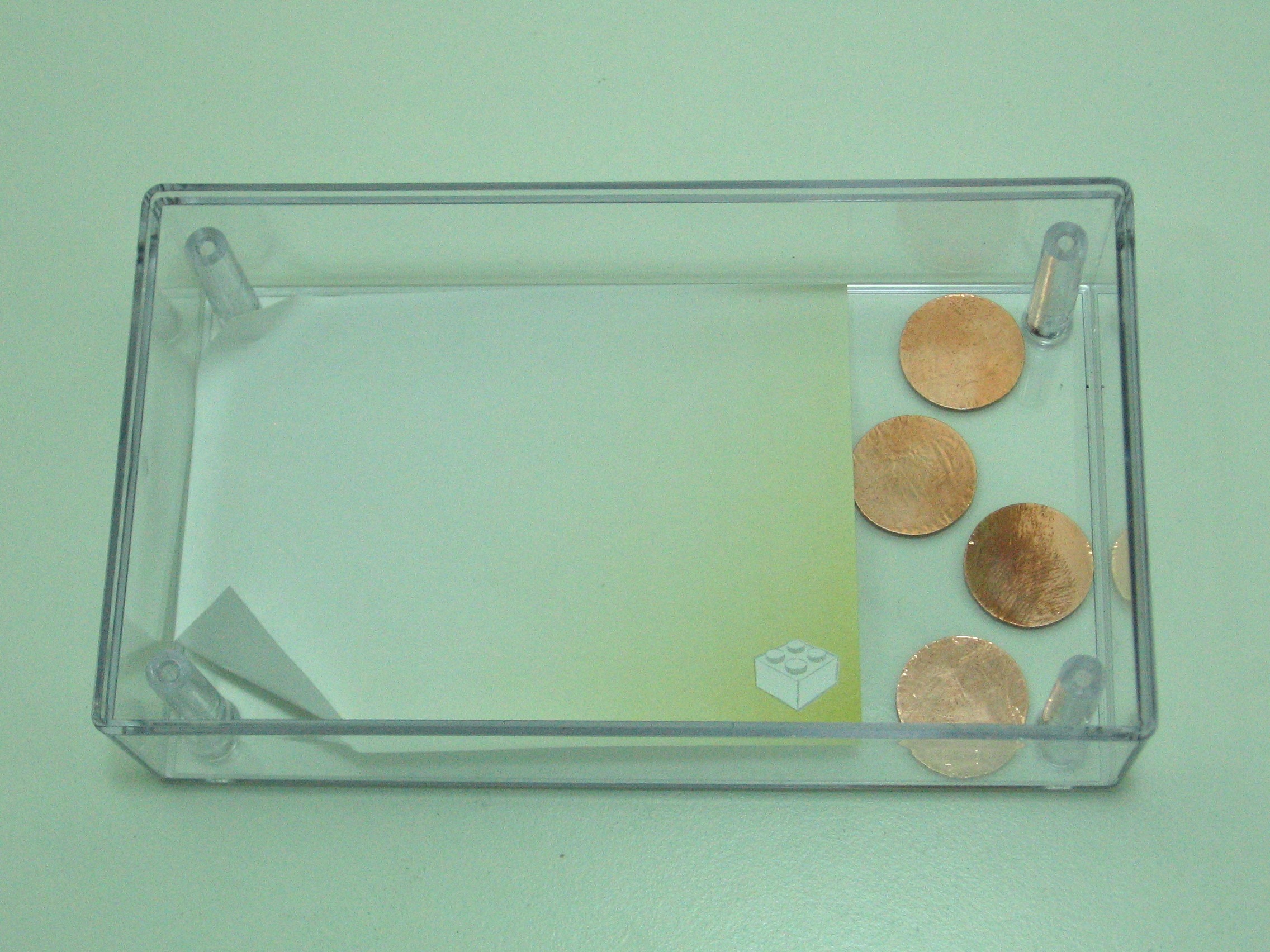
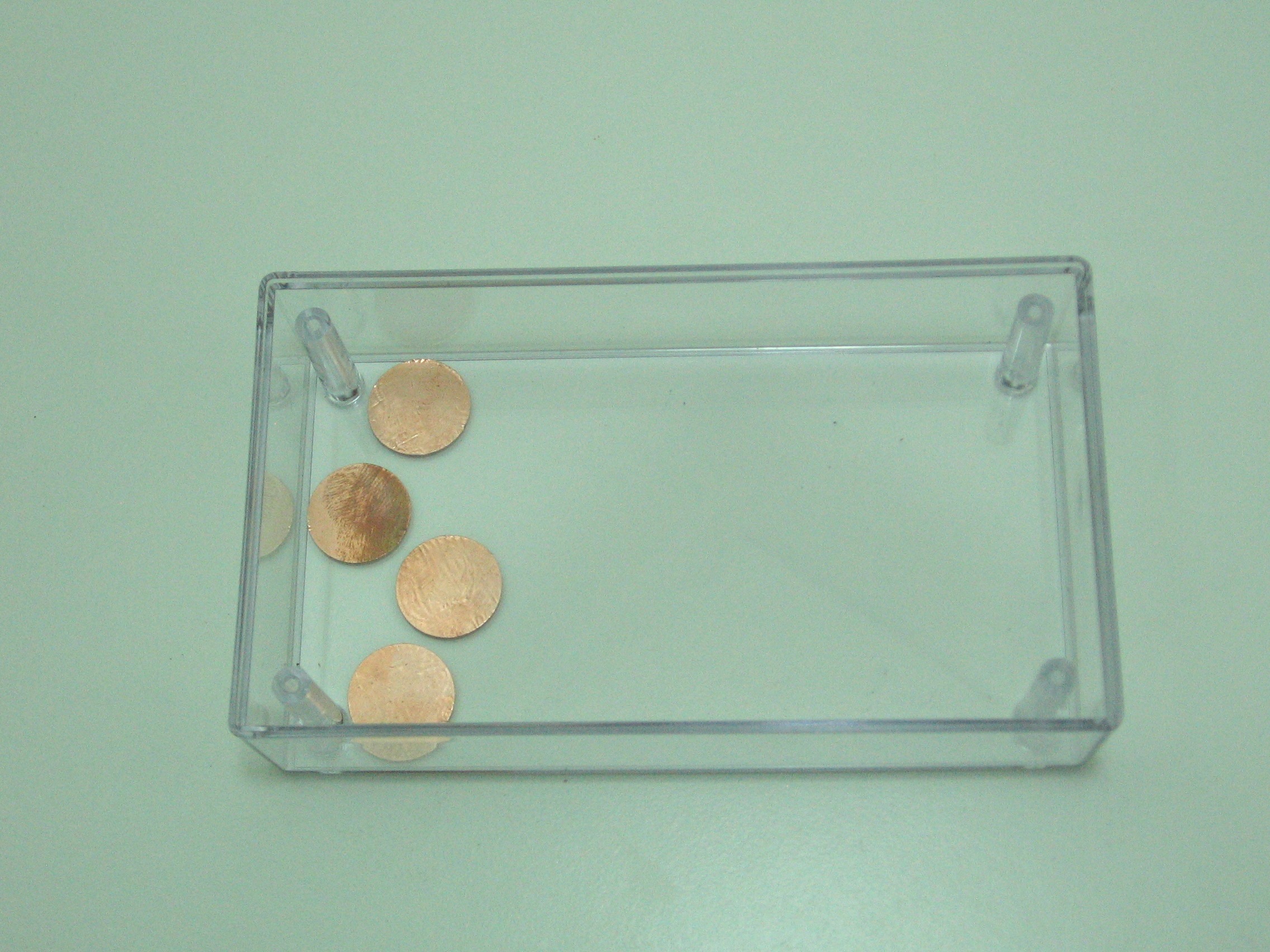
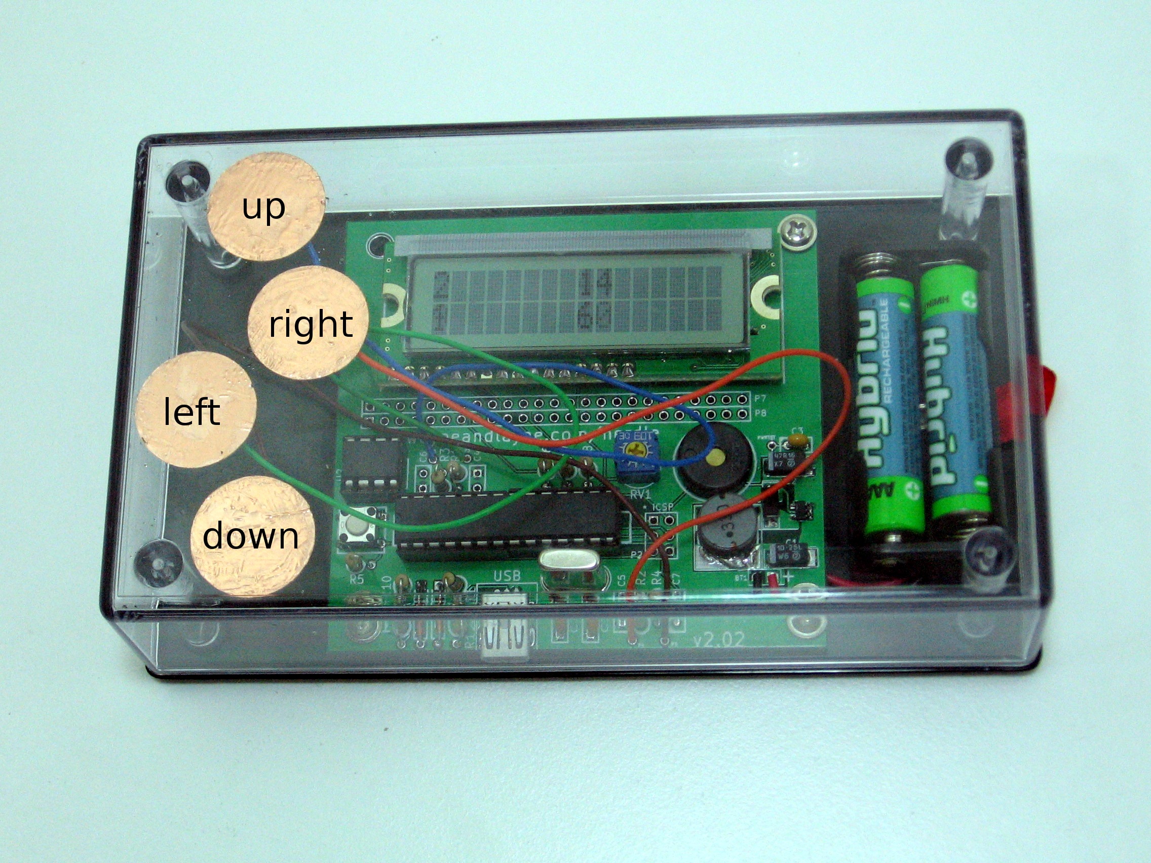
Carefully peel the copper foil from the backing. One side is sticky. Put the sticky side down on the inside of the case. Plan out your button arrangement before putting any foil down! There is an up, down, left, and right button. Make sure not to cover the display!
When placing the buttons, make sure you don’t touch the sticky side. The adhesive holds the button to the case, and if the oil from your fingers gets on that side, the buttons won’t stick as well. Use your fingernail to press down on the edges of the button to ensure a good attachment.
Solder contains metal, and a substance called flux. The flux helps the metal flow, but it can “pop” and make things messy. Normally, we don’t care about the flux making a mess, or remove it with some rubbing alcohol. However, we don’t want drops of flux splattered over our case. Use a piece of paper as a shield to protect the case from stray flux splatters.
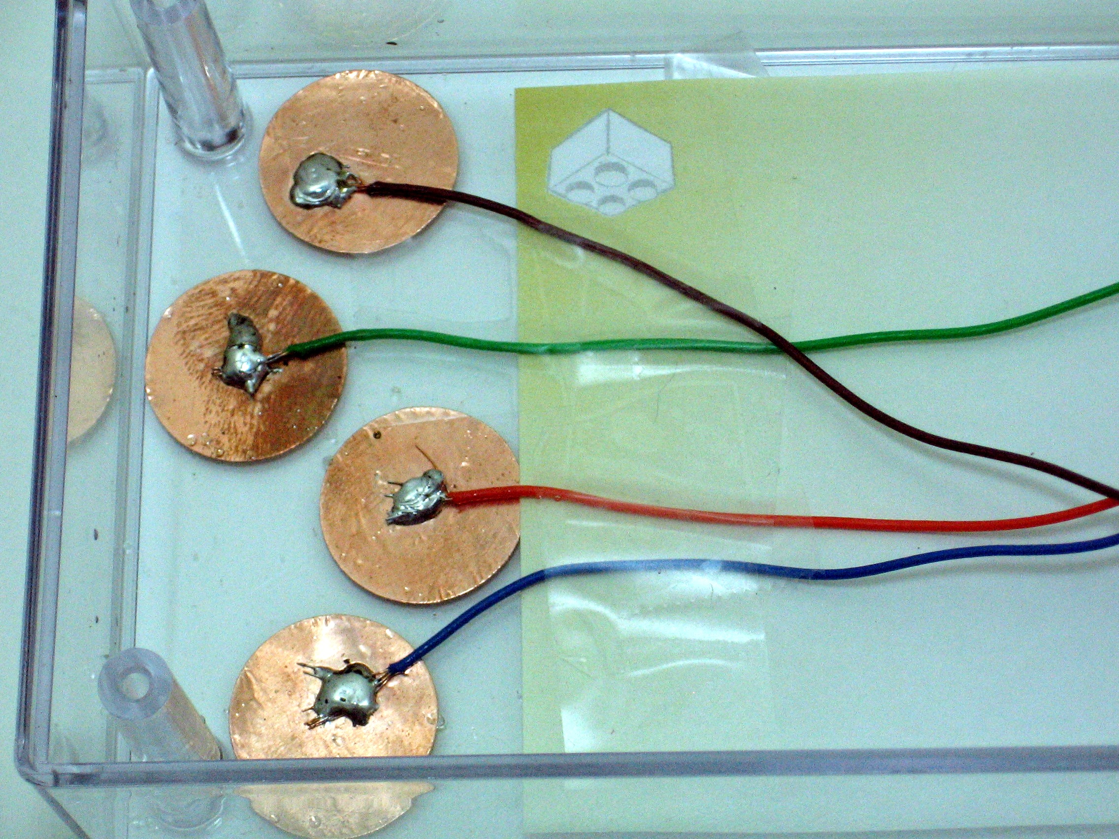
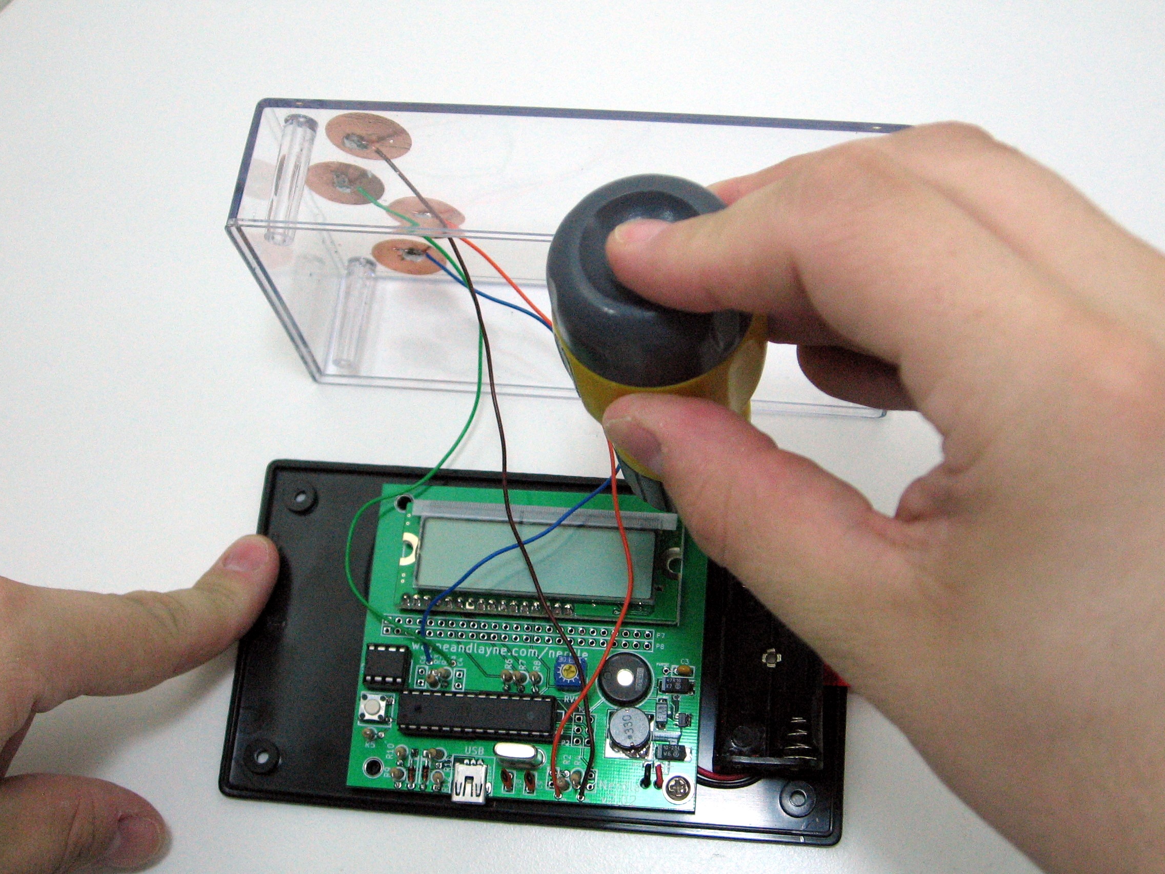
Trim a little bit of the insulation from both ends of the stranded wire. Spread the strands of one end out over the center of the pad. Make sure the wires don\’t go over any other pads than their own, and tape them down to the paper. We don\’t want them moving when we\’re soldering–it will make a weak connection and your buttons won\’t work.
Normally, it is very bad to “drop” solder from the end of your iron to any components. However, this is a special circumstance. Hold your iron just a bit above the wires, and push solder onto the tip of the iron. Let the solder blob drop onto the pad. Spread the solder out as needed. The wires need to be solidly connected to the pads, but holding the iron to the copper pads for too long will start to melt the case!

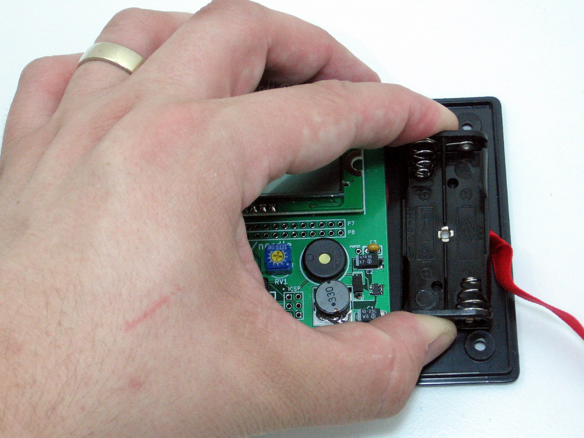
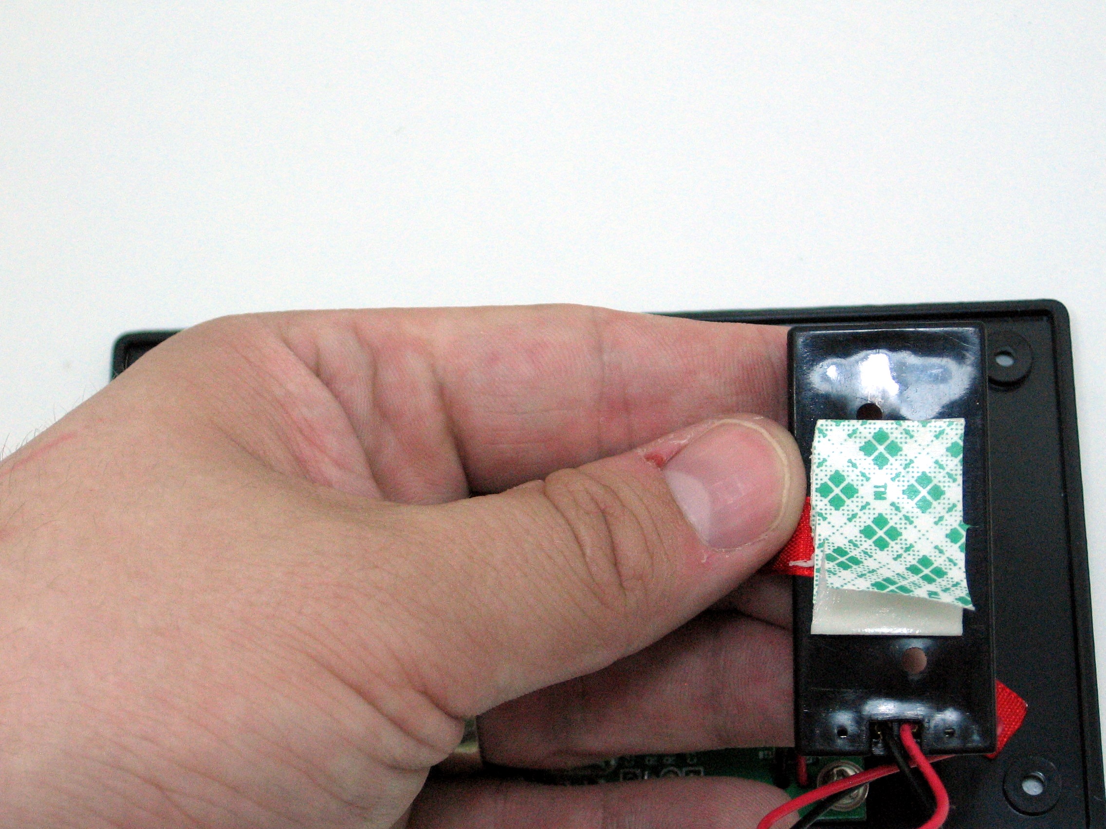
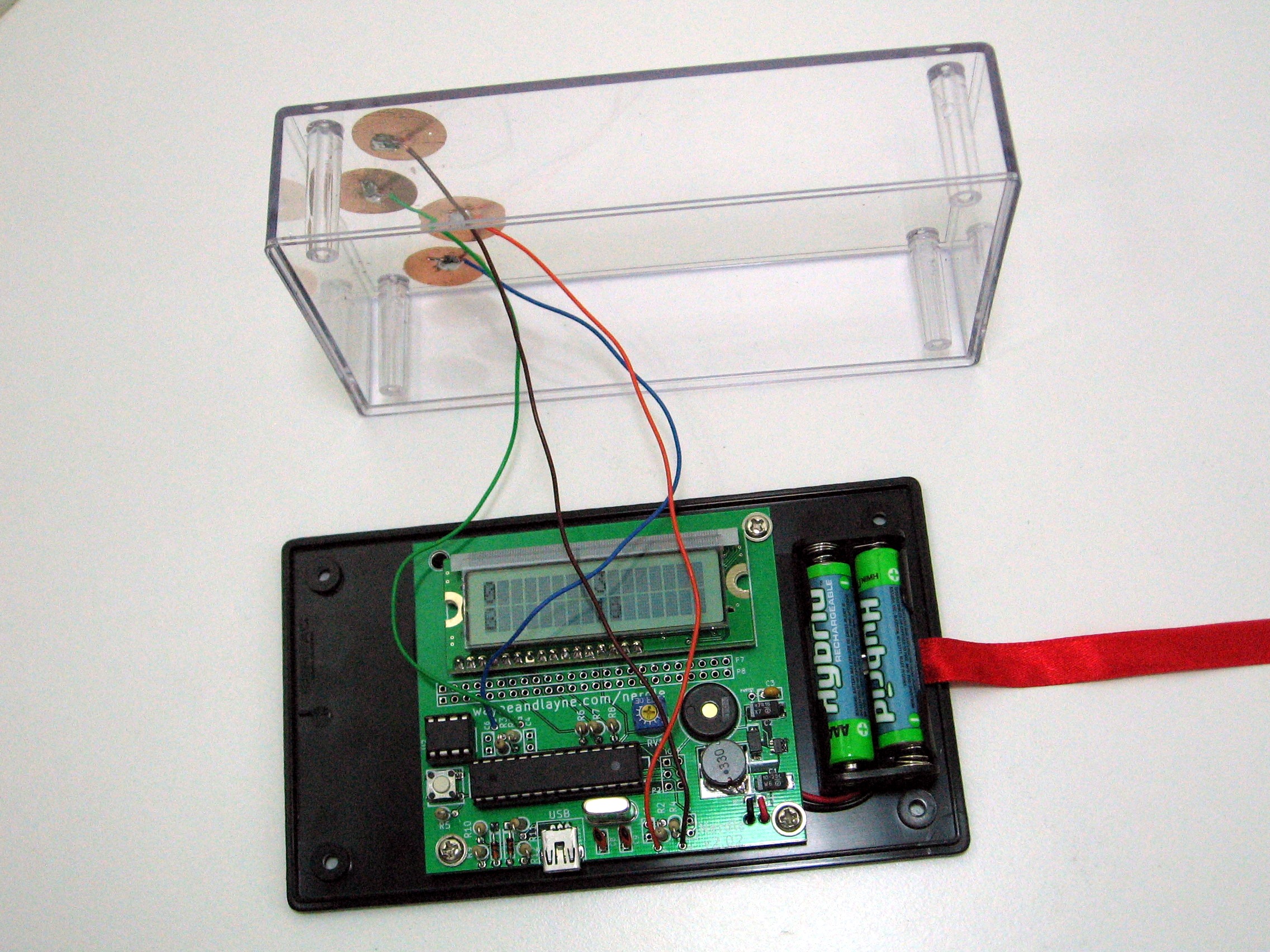
Remove the paper backing from the sticky tape on the battery holder. Place the Nerdle PCB over the mounting holes and press the battery holder down next to the PCB.
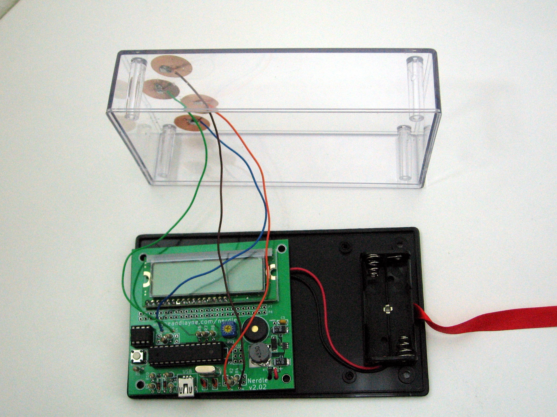
Next, solder the other end of the wires to the board. The holes are labeled P3, P4, P5, P6. Be sure to follow the following scheme: P3 = left, P4 = right, P5 = up, P6 = down Screw the board into the back panel.
Put the batteries in. The build is complete!
Before you screw the top of the case in, it’s time to put some software on the Nerdle!

H