Minco Million Flex Trade Show Demo
We haven’t been able to talk about many of the contract projects at Wayne and Layne, but we’re starting to change that!
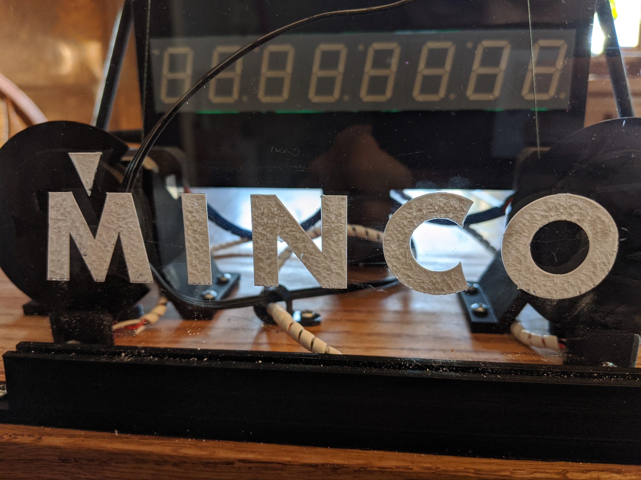
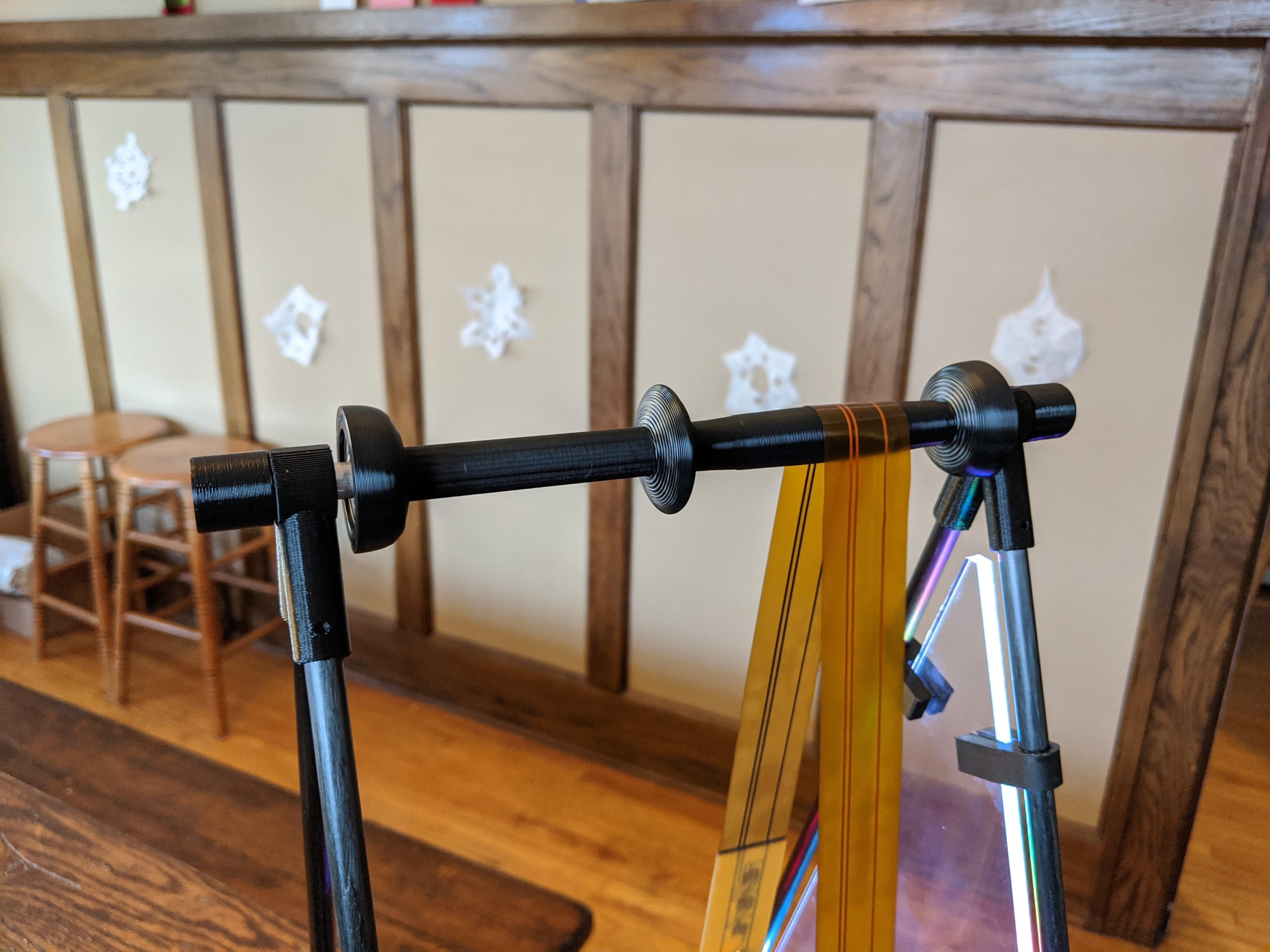
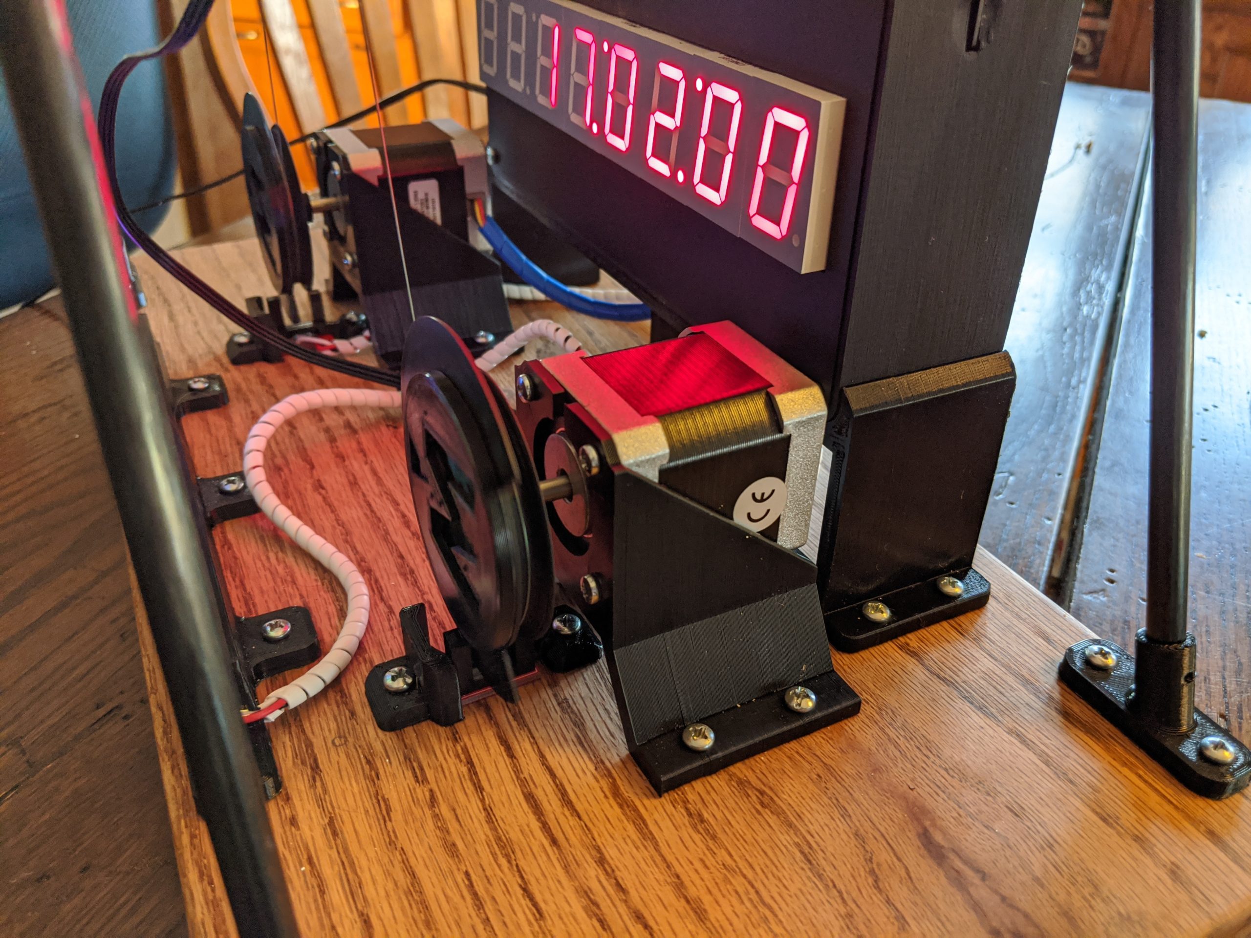
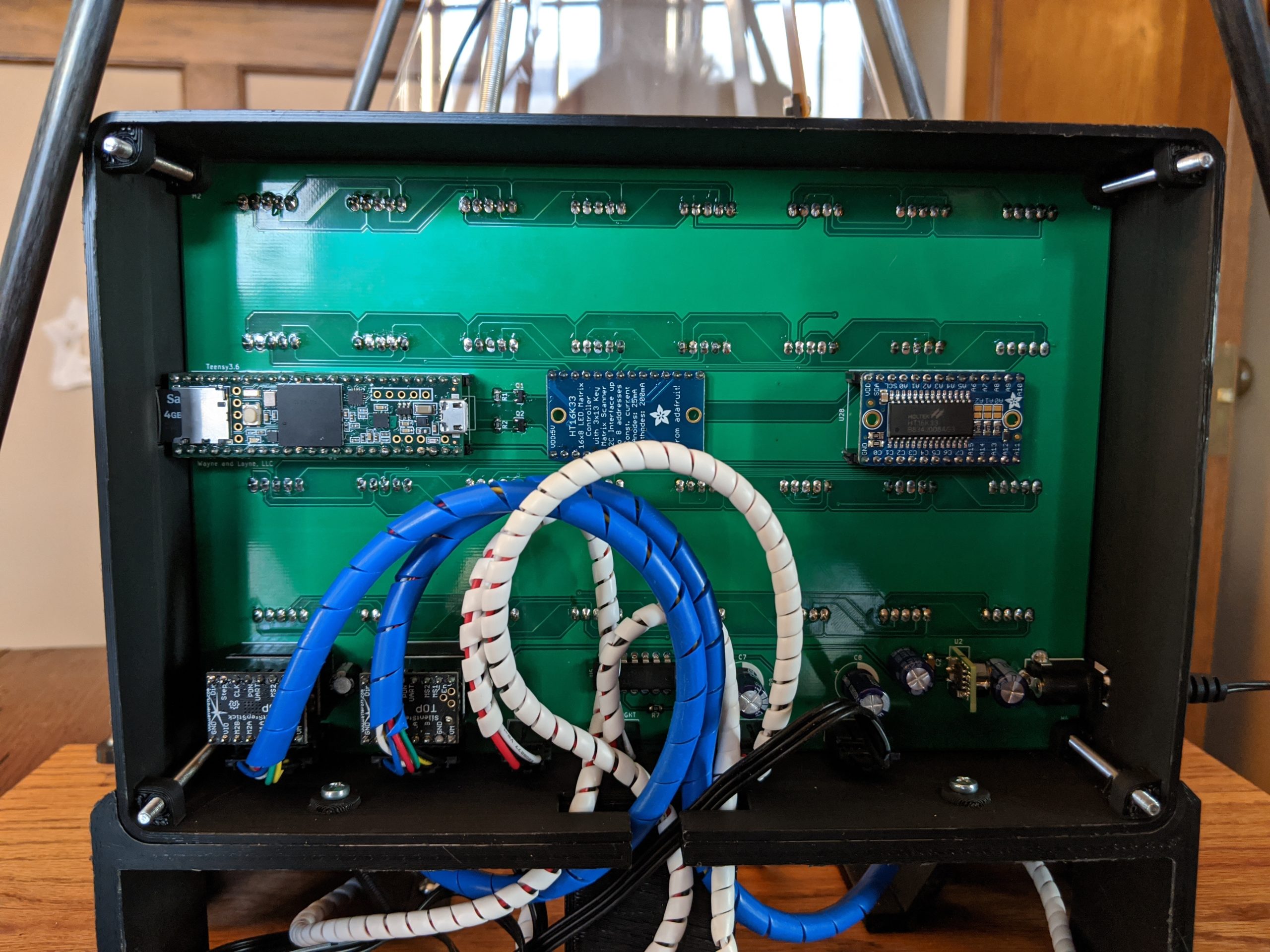
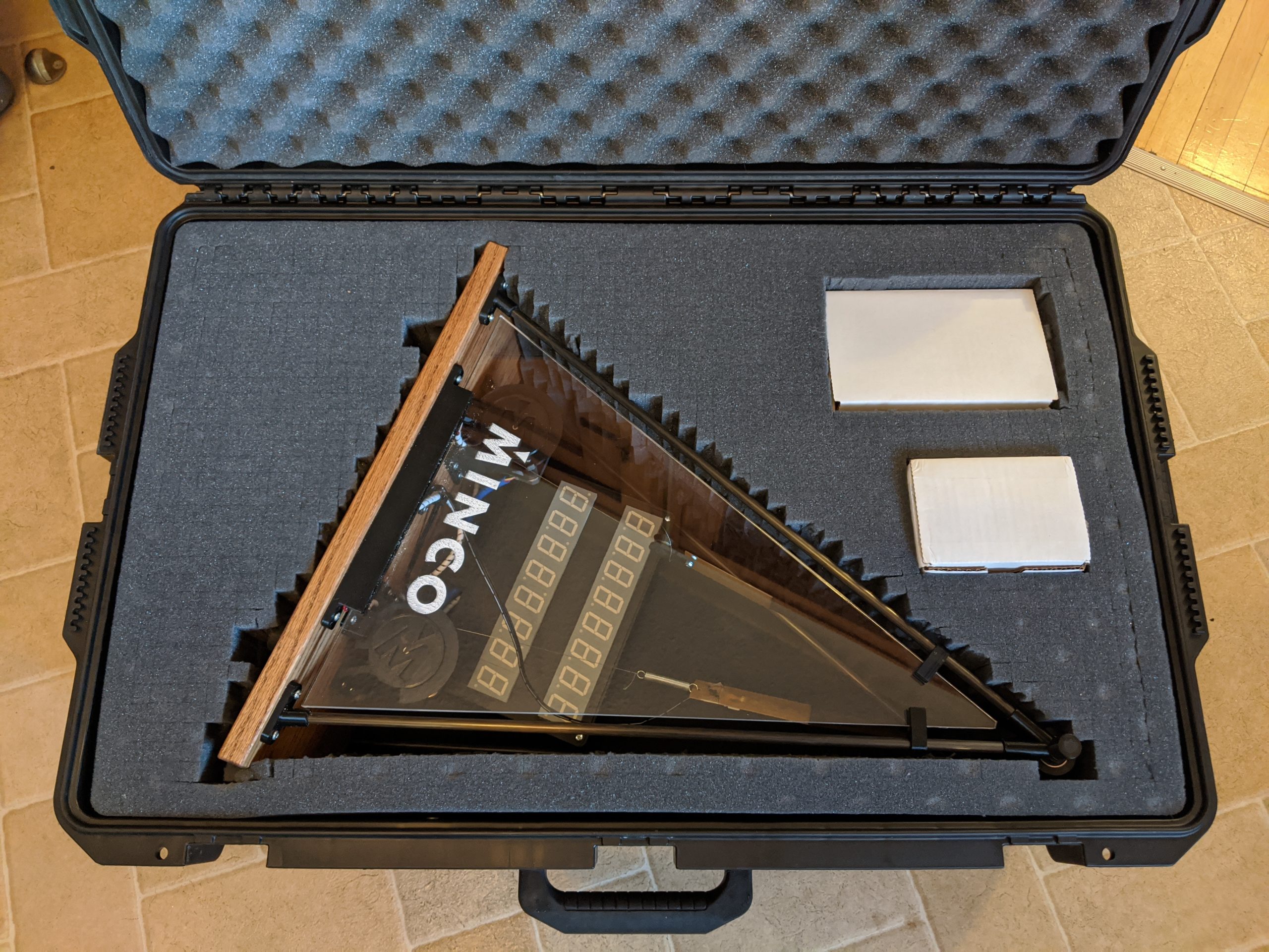
Minco is an engineering company in Fridley that really does a lot–flex PCBs, heaters, temperature sensors… They hired Wayne and Layne to make a flashy trade show demo, which would repeatedly flex one of their flex circuits over a roller. It keeps track of the total run time and number of flexes, and it needs to be able to track more than a million flexes before rolling over.
It’s got an edge-lit laser-etched acrylic face that’s lit in an ever-changing rainbow, big chonky seven-segment displays, carbon fiber rods, and with its fancy Trinamic motor drivers, it’s very quiet. Many of the parts are 3D printed, which really helped speed up development time.
Take a look!

If this looks like something you need, get in touch!
Blinky Flasher sketch for Arduino IDE
We recently started selling pre-assembled Blinky kits. As part of the manufacturing process, we really want to test out the optical programming process, to ensure that all the parts are working correctly. It would be inconvenient to dedicate a computer just to run the Blinky Programmer webpage to test each kit, so we decided to build a dedicated Blinky Flasher using an Arduino and two LEDs.
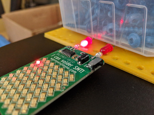
Here’s the simple sketch that transmits the pre-loaded data through the two LEDs. The code is also posted to our GitHub repository too.
/* Blinky Flasher
 * This sketch runs on an Arduino or compatible, with two LEDs.
 * It outputs the optical Clock / Data flashes to reprogram a blinky kit.
 *
 * Comment/uncomment one of the bytes[] definitions below to choose between:
 * 1. Original messages loaded into a Blinky Grid kit
 * 2. Original messages loaded into a Blinky POV kit
 * 3. Some other byte stream from the Blinky Programmer webpage:
 *    https://www.wayneandlayne.com/blinky_programmer/?debug
 *    Press 'Go' and then copy/paste the numbers from the `xmit_data` box
 *    into the bytes[] array below.
 *
 * The bytes are flashed-out once at power-up, then it stops until reset.
 * When it's done, the Arduino's built-in LED will start flashing.
 * Press the reset button to reset the Arduino and retransmit.
 *
 * More details about the Blinky message structure, framing, and transmission:
 * https://www.wayneandlayne.com/projects/blinky/design/#message
 *
 * Written by Matthew Beckler and Adam Wolf, for Wayne and Layne, LLC.
 * To the extent possible under law, Wayne and Layne, LLC has waived all
 * copyright and related or neighboring rights to Blinky Flasher.
 * This work is published from: United States.
 * More details: https://creativecommons.org/publicdomain/zero/1.0/
 */

/* Adjust these defines to match your LED connections.
 * This sketch assumes that HIGH output turns on each LED. */
#define PIN_CLOCK 14
#define PIN_DATA 16

/* Adjust this define to change the delay between LED state changes.
 * We've had reliable transmission with this set to 20. */
#define DELAY_MS 20

// The setup function runs once when you press reset or power the board
void setup() {
    // initialize digital pin LED_BUILTIN as an output.
    pinMode(LED_BUILTIN, OUTPUT);

    pinMode(PIN_CLOCK, OUTPUT);
    pinMode(PIN_DATA, OUTPUT);

    digitalWrite(PIN_CLOCK, LOW);
    digitalWrite(PIN_DATA, LOW);


    Serial.begin(9600);
}


// These are not message_data, they are xmit_data (including intel hex record framing)


// grid:
byte bytes[] = {16,0,0,6,8,230,14,170,85,170,85,170,85,170,85,170,85,170,85,170,74,16,0,16,6,85,10,11,17,14,21,21,24,41,32,24,27,21,13,234,7,128,16,0,32,6,4,98,97,9,97,98,4,10,11,32,10,34,23,14,38,21,114,16,0,48,6,10,34,23,14,222,14,48,72,68,34,68,72,48,48,120,124,191,16,0,64,6,62,124,120,48,10,34,11,21,18,23,20,34,41,16,27,18,55,16,0,80,6,13,41,18,28,41,10,41,28,22,10,27,29,41,21,14,13,13,16,0,96,6,41,22,10,29,27,18,33,37,10,40,11,21,18,23,20,34,0,16,0,112,6,41,16,27,18,13,41,32,10,28,41,22,10,13,14,41,11,0,16,0,128,6,34,41,32,10,34,23,14,41,10,23,13,41,21,10,34,23,214,16,0,144,6,14,37,10,60,11,21,18,23,20,34,41,16,27,18,13,41,198,16,0,160,6,18,28,41,27,14,25,27,24,16,27,10,22,22,14,13,41,217,16,0,176,6,11,34,41,17,24,21,13,18,23,16,41,18,29,41,30,25,168,16,0,192,6,41,29,24,41,34,24,30,27,41,28,12,27,14,14,23,37,108,0,0,0,1,255};


// pov:
//byte bytes[] = {16,0,0,6,6,145,16,24,60,62,31,62,60,24,0,96,240,248,124,248,68,16,0,16,6,240,96,0,33,10,11,21,18,23,20,34,41,25,24,31,145,214,16,0,32,6,14,128,64,32,16,8,4,2,1,2,4,8,16,32,64,17,46,16,0,48,6,7,17,14,21,21,24,41,41,253,14,170,85,170,85,170,85,248,11,0,64,6,170,85,170,85,170,85,170,85,211,1,170,53,0,0,0,1,255};


// other:
//byte bytes[] = {8,0,0,6,1,30,5,17,14,21,21,24,109,0,0,0,1,255};


// the loop function runs over and over again forever
void loop() {
    Serial.println("");
    for (unsigned int byix = 0; byix < sizeof(bytes); byix++) {
	Serial.print("\n");
	Serial.print(bytes[byix], HEX);
	Serial.print("  ");
	for (signed int btix = 7; btix >= 0; btix--) {
	    // set data to black/white
	    if (bytes[byix] & (1 << btix)) {
		Serial.print("1,");
		digitalWrite(PIN_DATA, HIGH);
	    } else {
		Serial.print("0,");
		digitalWrite(PIN_DATA, LOW);
	    }

	    // delay a few ms
	    delay(DELAY_MS);


	    // change clock state
	    digitalWrite(PIN_CLOCK, !digitalRead(PIN_CLOCK));


	    // delay a few ms
	    delay(DELAY_MS);
	}
    }


    // all done
    digitalWrite(PIN_CLOCK, LOW);
    digitalWrite(PIN_DATA, LOW);


    while (1) {
	digitalWrite(LED_BUILTIN, HIGH);   // turn the LED on (HIGH is the voltage level)
	delay(100);
	digitalWrite(LED_BUILTIN, LOW);    // turn the LED off by making the voltage LOW
	delay(100);
    }
}
Blinky kit assembly: New sensor strategy
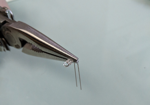
We recently had to assemble a few Blinky kits and found a quick and easy method of soldering the optical sensors.
The best way appears to be to first bend the leads by 90 degrees. Use a pliers and pinch the leads directly below the sensor body. Use the fingers of your non-pliers hand to bend the leads by 90 degrees. Be sure that you’re bending them the correct way, as the two sensors have different orientation (C sensor has longer lead on left, while D sensor has longer lead on right).
After the two sensors have been bent, drop them into their corresponding holes in the printed circuit board (PCB). If you suspend the PCB using a vice, then the sensors should stay in place, oriented so they are pointing away from the circuit board. Use a soldering iron to carefully solder each pin. If the sensor gets crooked while soldering, use the solder to gently nudge it back into place (while continuing to heat the soldered pad).
Wayne and Layne is proud to announce that we are now selling pre-assembled Blinky Grid SMT kits!
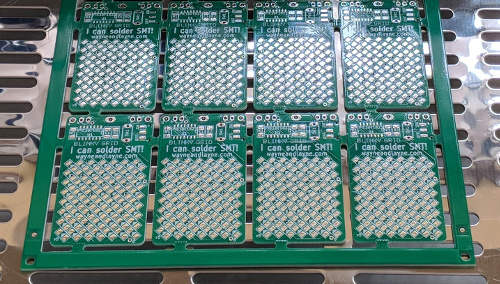
A few years ago we purchased some “panelized” circuit boards of the Blinky Grid SMT design, which means that there are several copies (16 in this case) of the same circuit board design connected together in a snap-apart panel. This makes it easier (and quicker!) to assemble the boards in bulk.
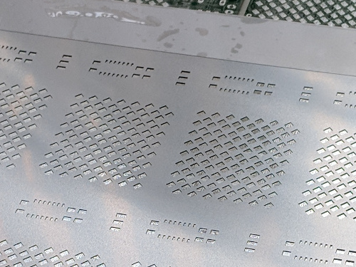
The first step in bulk assembly is to apply solderpaste to all the exposed pads on the circuit board. We purchased a stainless steel stencil that matches the 16-board panels, then used a squeegee to apply lead-free solder paste through the holes in the stencil.
After all the pads have solder paste, the next step is to place each part on the board, stuck down into the solder paste. To place the parts, we use a machine called a Pick-‘n-Place (PnP). This is a desktop computer-controlled robot with a small vacuum nozzle that can pick up a part, optionally rotate it, and place it down in a precise location on the circuit board. Here’s a two-minute video of the PnP machine in action:
After the parts have been placed on the board, we need to heat it up to melt the solder to attach the parts. We use a small soldering oven to do this.
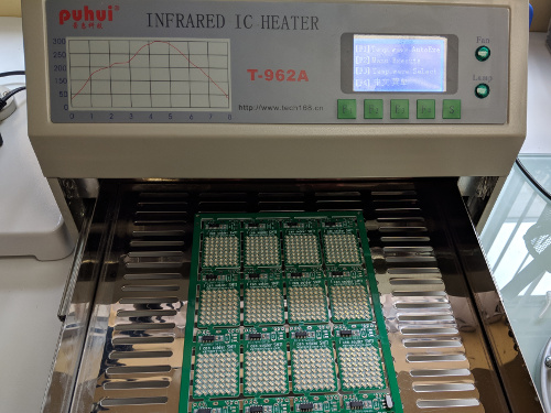
After the boards have been baked, the solder has melted and connected all the parts to the circuit board. The remaining steps include:
- Solder the through-hole parts, like the pushbutton and sensors
- Program the microcontroller with the Blinky Grid program code
- Test that everything works correctly, including programming
- Package and label each kit for sale
You can now find the pre-assembled Blinky Grid SMT kits in the Wayne and Layne Store.
This blog post is a short introduction to a pair of useful modes of operation for the Blinky Programmer webpage.
The standard Blinky Programmer webpage is a decent way to interactively create and program new messages into a Blinky Grid or Blinky POV kit. However, there are two main requests that we’ve received for new functionality for the programmer:
1. “How can I restore the original messages that were on the Blinky kit?”
2. “Is there any way I can save and restore the messages that I set up in the programmer webpage?”
Now, we have a way to do both of these!
First, a little background. The programmer webpage converts the messages that are created using the visual interface into a series of numbers, that are then optically transmitted to the Blinky kit. Details of the message formatting and transmission are available here.
The enhancements we’ve added are two-fold: First, we added a way to see “under the hood” of the blinky programmer webpage, so you can see the underlying data stream that is generated from the visual editor. This is a debug mode, enabled by adding “?debug” to the end of the website address, like this: https://www.wayneandlayne.com/blinky_programmer/?debug
When the debug mode is enabled, a few new text boxes appear at the bottom of the page. These boxes are initially blank, but are populated as soon as you press the Go button. The first two boxes show the raw message data as a series of bytes, separated by columns (first box is decimal, second box is hex). These are the bytes that we want to store into the Blinky kit (first byte indicates how many messages are included, followed by the bytes of each message in turn). The second set of boxes show the “packaged” data to transmit (“xmit”), which surrounds the message data with some meta-data about where the message data should go inside the chip, and adds a checksum to protect against transmission mistakes (basically, we are packing the message data into the Intel HEX file format. The final text box shows the raw binary equivalent of the packed xmit data, which is the string of ones and zeros that are actually flashed out by the webpage. The most useful box here is the “message_data:” text box.
The second enhancement is a new version of the Blinky programmer webpage that enables “raw” programming. The new raw programmer is located here: https://www.wayneandlayne.com/blinky_programmer/raw.php. “Raw” simply means that instead of using the visual editor to create text-based or pixel-based messages, you can simply type-in or copy-paste the message data into a text box, which will then be transmitted. This enables restoring the original set of messages, as well as being able to save your creations (by copying the contents of the “message_data” text box) and then pasting it into the raw programmer.
Back to the list of requested features, this time with some answers!
1. “How can I restore the original messages that were on the Blinky kit?”
Easy to do:
- Go to the raw programmer webpage.
- Copy-paste one of these long lists of numbers into the upper text field:
POV:
6, 145, 16, 24, 60, 62, 31, 62, 60, 24, 0, 96, 240, 248, 124, 248, 240, 96, 00, 33, 10, 11, 21, 18, 23, 20, 34, 41, 25, 24, 31, 145, 14, 128, 64, 32, 16, 8, 4, 2, 1, 2, 4, 8, 16, 32, 64, 17, 7, 17, 14, 21, 21, 24, 41, 41, 253, 14, 170, 85, 170, 85, 170, 85, 170, 85, 170, 85, 170, 85, 170, 85, 211, 01, 170
Grid:
8, 230, 14, 170, 85, 170, 85, 170, 85, 170, 85, 170, 85, 170, 85, 170, 85, 10, 11, 17, 14, 21, 21, 24, 41, 32, 24, 27, 21, 13, 234, 7, 4, 98, 97, 9, 97, 98, 4, 10, 11, 32, 10, 34, 23, 14, 38, 21, 10, 34, 23, 14, 222, 14, 48, 72, 68, 34, 68, 72, 48, 48, 120, 124, 62, 124, 120, 48, 10, 34, 11, 21, 18, 23, 20, 34, 41, 16, 27, 18, 13, 41, 18, 28, 41, 10, 41, 28, 22, 10, 27, 29, 41, 21, 14, 13, 41, 22, 10, 29, 27, 18, 33, 37, 10, 40, 11, 21, 18, 23, 20, 34, 41, 16, 27, 18, 13, 41, 32, 10, 28, 41, 22, 10, 13, 14, 41, 11, 34, 41, 32, 10, 34, 23, 14, 41, 10, 23, 13, 41, 21, 10, 34, 23, 14, 37, 10, 60, 11, 21, 18, 23, 20, 34, 41, 16, 27, 18, 13, 41, 18, 28, 41, 27, 14, 25, 27, 24, 16, 27, 10, 22, 22, 14, 13, 41, 11, 34, 41, 17, 24, 21, 13, 18, 23, 16, 41, 18, 29, 41, 30, 25, 41, 29, 24, 41, 34, 24, 30, 27, 41, 28, 12, 27, 14, 14, 23, 37 - Scroll down and press the Go button to begin transmission.
2. “Is there any way I can save and restore the messages that I set up in the programmer webpage?”
Definitely possible:
- Using the normal Blinky Programmer webpage, but add “?debug” to the end of the address, like this: https://www.wayneandlayne.com/blinky_programmer/?debug
- Create your text-based or pixel-based messages like normal. Transmit them into your Blinky kit to double-check that the message is correct.
- Select all the text in the “message_data” text box and copy-paste it into a separate document on your computer that you can save and access later.
- When you’re ready to program one of your old saved messages, go to the raw programmer webpage.
- Copy-paste one of your saved messages into the upper text box.
- Scroll down and press the Go button to begin transmission.
Hope that helps! If you have any questions, please ask in the forum or contact us.
The Blinky kits each contain a microcontroller, which is a type of reprogrammable computer chip that can loaded with new code whenever you want. The chip used in each Blinky kit is the PIC16F1823 (PDF datasheet), a general-purpose 8-bit microcontroller made by Microchip.
Each chip contains two types of non-volatile memory for storing data. Here, non-volatile means that the stored data is not lost when the power is turned off. The two types of non-volatile memory are:
- Flash memory, like in a USB pocket drive, stores the main programming code in compiled form. The code is read and executed when the chip is running. The flash memory contains two separate programs: The bootloader (used for reprogramming) and the main code (reads messages from EEPROM and displays them on the LEDs). More details on the design page.
- EEPROM (Electronically-Erasable Programmable Read-Only Memory) stores the messages that are displayed on the Blinky kit’s LEDs. The “read-only” part of the name is a bit of a misnomer but is kept for historical reasons (Wikipedia has more details).
The typical use case for a Blinky kits is to use the nifty optical reprogramming system to update the messages stored in EEPROM, without changing the flash memory. If you want to change the bootloader or the main code stored in flash memory, you’ll need to use a separate process called ICSP (In-Circuit Serial Programming). ICSP requires a hardware programmer, which is typically a USB device used to interface between a computer and the flash memory inside the microcontroller. There are many different types of hardware programmers but our favorite for PIC processors is the PICkit2 (now retired) and PICkit3. They are quite reasonably priced and work great on Windows, OSX, and Linux.
To reprogram a PIC microcontroller with an ICSP hardware programmer requires software on a computer to talk to the programmer, plus five electrical connections between the hardware programmer and the PIC chip. These electrical connections are specified in the ICSP protocol document, and are:
- MCLR / Vpp – Goes to the PIC’s reset pin. Allows the programmer to reset the chip, and provide the high voltage (Vpp) that switches the chip into flash programming mode.
- VDD – This is the chip’s normal power supply connection (usually 3-5 volts). Allows the programmer to either power the PIC itself, or to know what voltage level the PIC is being powered with externally.
- VSS – This is the chip’s normal ground (0 volt) power supply connection. The chip and the programmer need to agree on the ground reference voltage.
- ICSPDAT – Once the programmer switches the chip into flash programming mode, it sends commands and data using a two-wire protocol. This is the data pin of that two-wire protocol.
- ICSPCLK – This is the clock pin of the two-wire protocol.
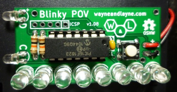
On the non-SMT Blinky kits (the Blinky Grid and Blinky POV), the ICSP signals are conveniently wired to a five-pin header row along the edge of the circuit board as shown in the image below. You can solder header pins or wires to these holes to connect your ICSP hardware programmer.
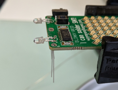
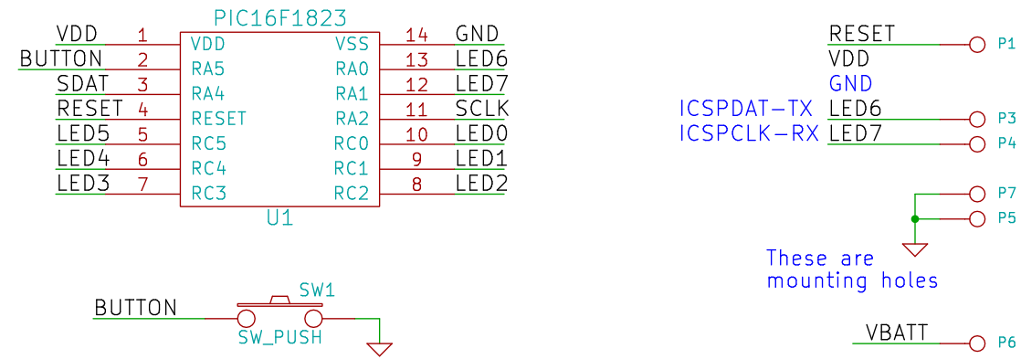
On the SMT Blinky kits (the SMT Blinky Grid and SMT Blinky POV, there wasn’t enough room to put the five pins together, but you can still reprogram the PIC chip. Option 1 is to attach test leads to the five pins on the PIC itself:
- Chip pin 4 – MCLR / Vpp (reset/programming)
- Chip pin 1 – VDD (power supply)
- Chip pin 14 – VSS (ground)
- Chip pin 13 – ICSPDAT / UART TX / LED 6 (programming data)
- Chip pin 12 – ICSPCLK / UART RX / LED 7 (programming clock)
Here’s the relevant part of the circuit schematic for reference (click to enlarge). The full schematics are available at the download page.
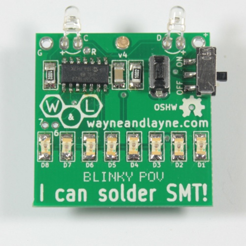
Option two is to solder wires into these labeled holes:
- “R” – MCLR / Vpp (reset/programming)
- “+” – VDD (power supply)
- “G” – VSS (ground)
- “6” – ICSPDAT / UART TX / LED 6 (programming data)
- “7” – ICSPCLK / UART RX / LED 7 (programming clock)
Once the five ICSP connections are made to the circuit board, use the PICkit software to program a HEX file into the chip. We have all the firmware hex files posted here on the Blinky download page.
I wanted to learn how to design physical objects in 3D mechanical CAD, so I started to learn Autodesk Fusion 360. It’s free for “students, enthusiasts, hobbyists, and startups”, but cloud based and closed source, so it could be vastly more limited since this blog post was written in November 2016. It might be a better idea to try to learn (and maybe contribute to) one of the open source mechanical CAD packages like FreeCAD, but a good friend of mine had good luck with Fusion 360 so I went with that.
To start with, I’ve never used a parametric 3D modeler before, so I am probably doing everything wrong. Here are some of the tutorials I followed:
- Get started with Fusion 360 – 12 tutorials in under 60 minutes
- Fusion 360 Tutorials (with actually-useful video/screencasts)
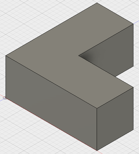
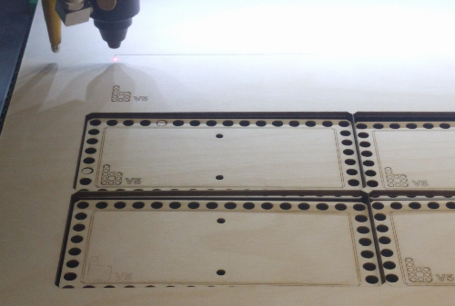
I wanted to design something simple as my first project in Fusion 360. We do a reasonable amount of laser cutting at W&L, and I’ve noticed that the work-pieces sometimes get little scorch marks where the laser hits the aluminum hexagonal support structure underneath. Our most common piece of stock is 12x12x1/3 inch baltic birch plywood, and I though it might be cool to design and 3D print some simple pieces to support the wood from the corners, to avoid scorch marks and to allow the little cutout pieces to fall through. I had envisioned an L-shaped piece with a ledge for the wood to sit. Maybe with a hole in the corner in case we want to add a screw to hold the wood to the support (if gravity isn’t enough).
If you want to follow-along in Fusion 360, here is a link to the design, where you can download it in Fusion 360 format, STL, or any other of a large number of formats.
As far as I have learned, this kind of 3D CAD tool is organized as a sequence of sketches (where you draw points and lines in a 2D plane) and “actions” (probably the wrong word) such as extrude and fillet. Parametric modelers are cool because you can define parameters, then use those parameters to adjust dimensions in your sketch. This makes it easy for your designs to be flexible, where you can define a “bolt diameter” parameter and adjust if you need to change to metric hardware (for example).
For this simple design I had three sketches, three cuts/extrusions, and one unnecessary and flamboyant fillet 🙂 . I’ll go through each step in this blog post. Again, this is probably a non-optimal way to do this kind of thing.
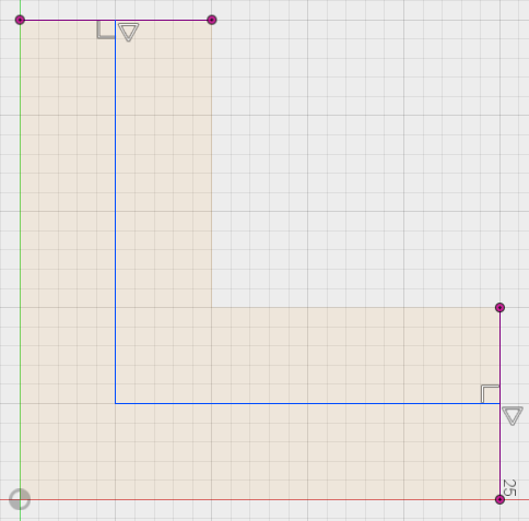
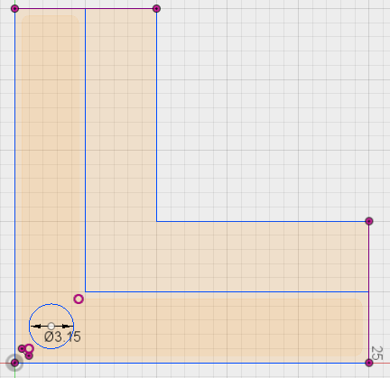
Sketch 1: The bottom of the thing

Another cool thing about this kind of parametric modeler is that you can specify all sorts of constraints in the sketch, and it will adjust the sketch based on changing parameters. For example, you can add a right-angle constraint between two lines. If you then rotate one of the lines, the system will do its best to keep the lines at a right angle. In the sketch above, you can see some right-angle constraints and a vertical constraint. The overall dimensions are 25 x 25 mm.
Extrude 1
I extruded the L-shaped Sketch upward in the vertical direction by 10 mm.
Sketch 2: Building a shelf area
Here I added lines down the middle of each “arm” of the L-shape. This way I can extrude part back down to the create a little shelf for the wood.
Extrude 2
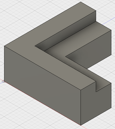
I did an extrude (technically a cut) downward to create the little shelf.
Fillet
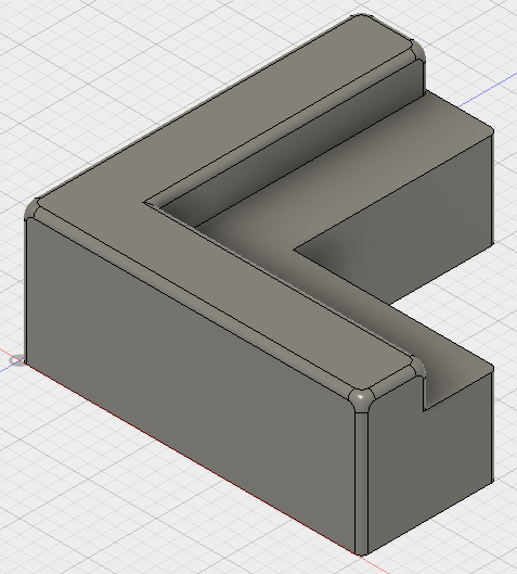
A fillet is “a rounding of an interior or exterior corner of a part design” (from Wikipedia), added to help reduce drag, improve mechanical strength, and just make the part look fancy and professional! Here I added a fillet with 0.5 mm radius. I did not apply the fillet to the bottom or the support surface under the wood.
Sketch 3: Adding a hole just in case
I thought maybe we might want to add a screw in the corner to help hold down the work-piece. Easy enough to add at this stage.
Extrude 3
The hole is cut/extruded through the whole piece.
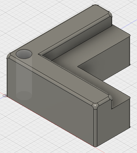
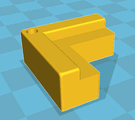
3D Printing
Using the Make –> 3D Print menu we can export an STL file suitable for 3D printing.
Results
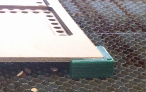
The four corner holders work quite well for elevating the work-piece above the cutting bed. The small pieces fall through and don’t interfere with the cutting head. The larger pieces don’t get any scorch marks when they are cut out.
Conclusion
Overall, this was a fun thing to design and a decent way to gain experience with Fusion 360 for 3D modeling. Next time I might make the support taller than 10 mm to give more clearance for falling parts.
The latest update to the Bricktronics 6xAA Battery Holder mounting plate (v6) has been released. This version adds four new mounting holes for an alternate battery holder. Our original pick, Eagle Plastic Devices 12BH361A-GR (apparently a Mouser house-brand), has been sporadically out of stock in 2016, so we wanted to find a second source for this part. Memory Protection Devices BH36AAW (DigiKey part BH36AAW-ND) is a pretty good replacement, but has different mounting holes. Version 6 of this mounting plate adds those needed holes.
In the image below, the new design is shown on top, the middle is the original EPD battery holder mounted to the v4 mounting plate, and the bottom is the new MPD battery holder.
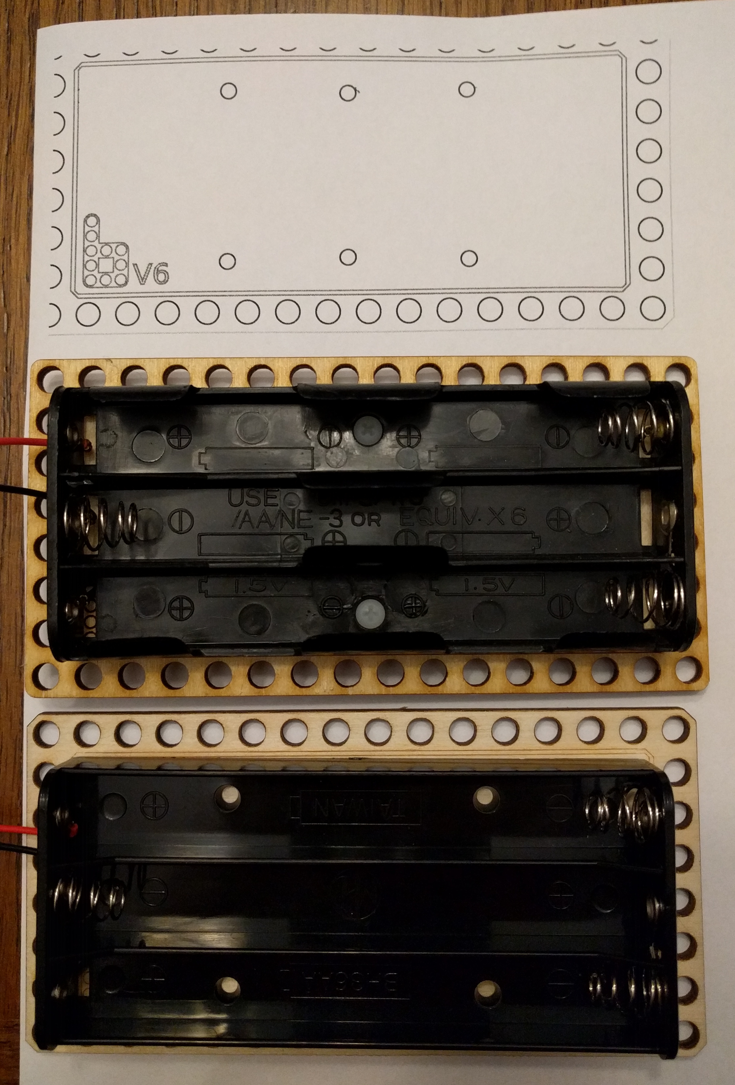
Download SVG and PDF of new design from our GitHub repository.
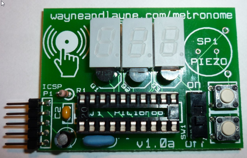
Seven years ago today
My photo manager just reminded me that this photo was taken seven years ago today. It’s a photo of the first version of the metronome kit.
Laser Cut Project Plate
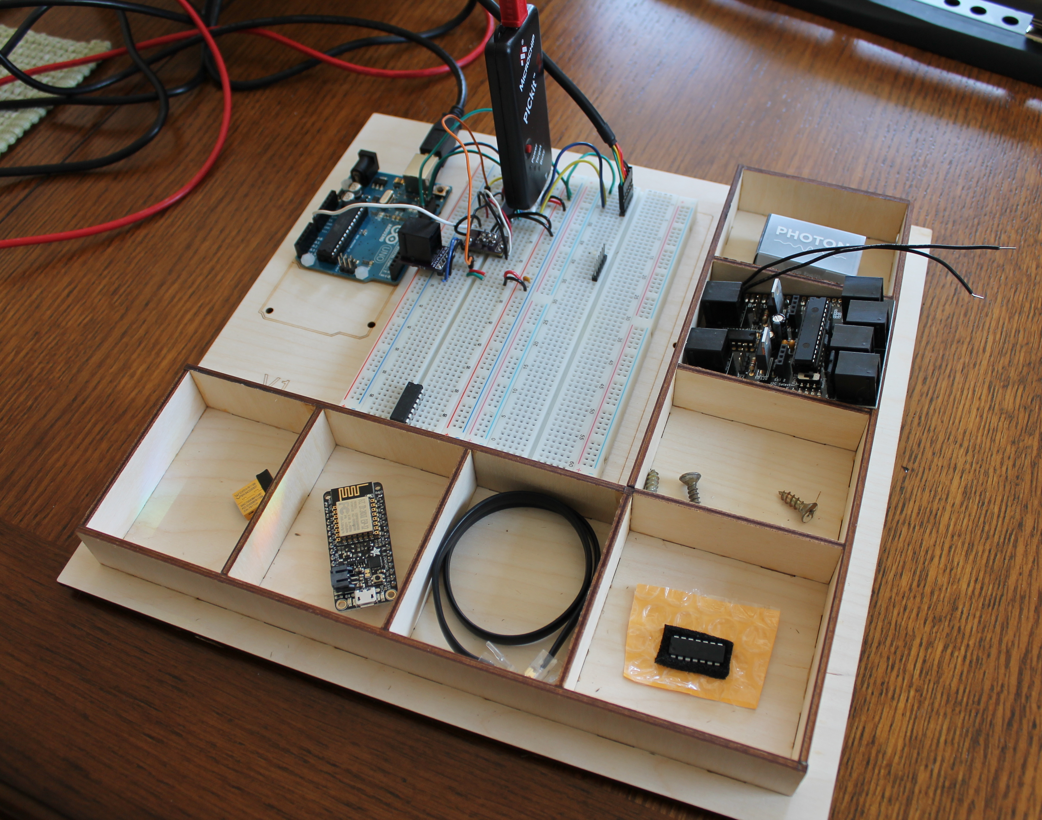
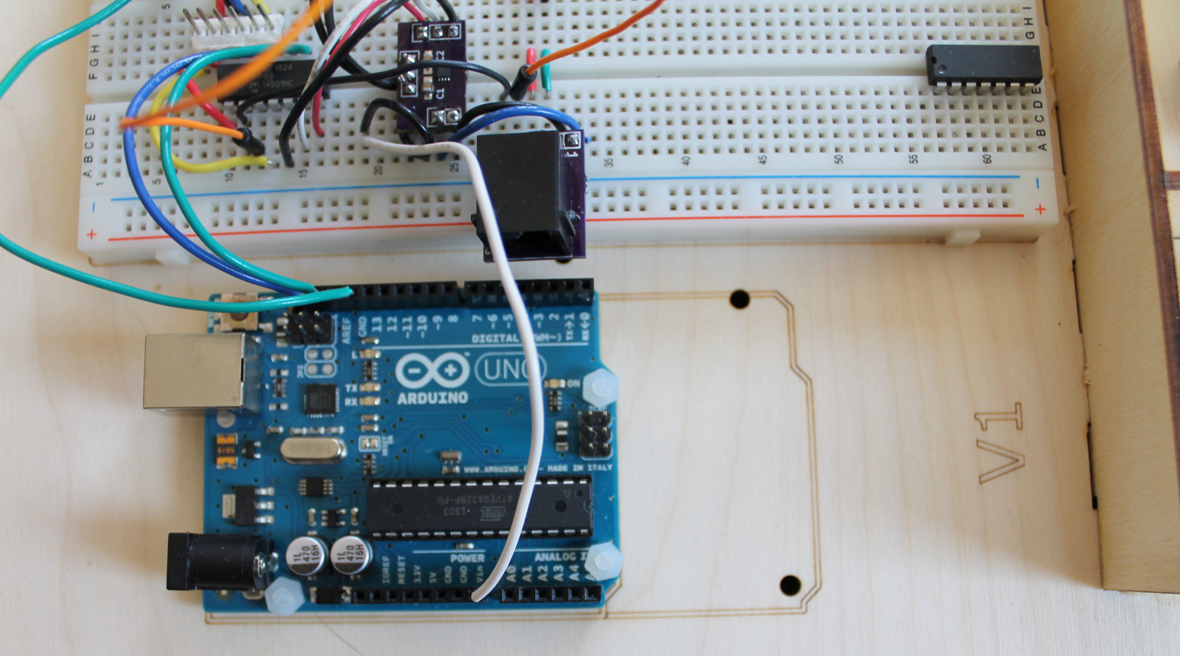
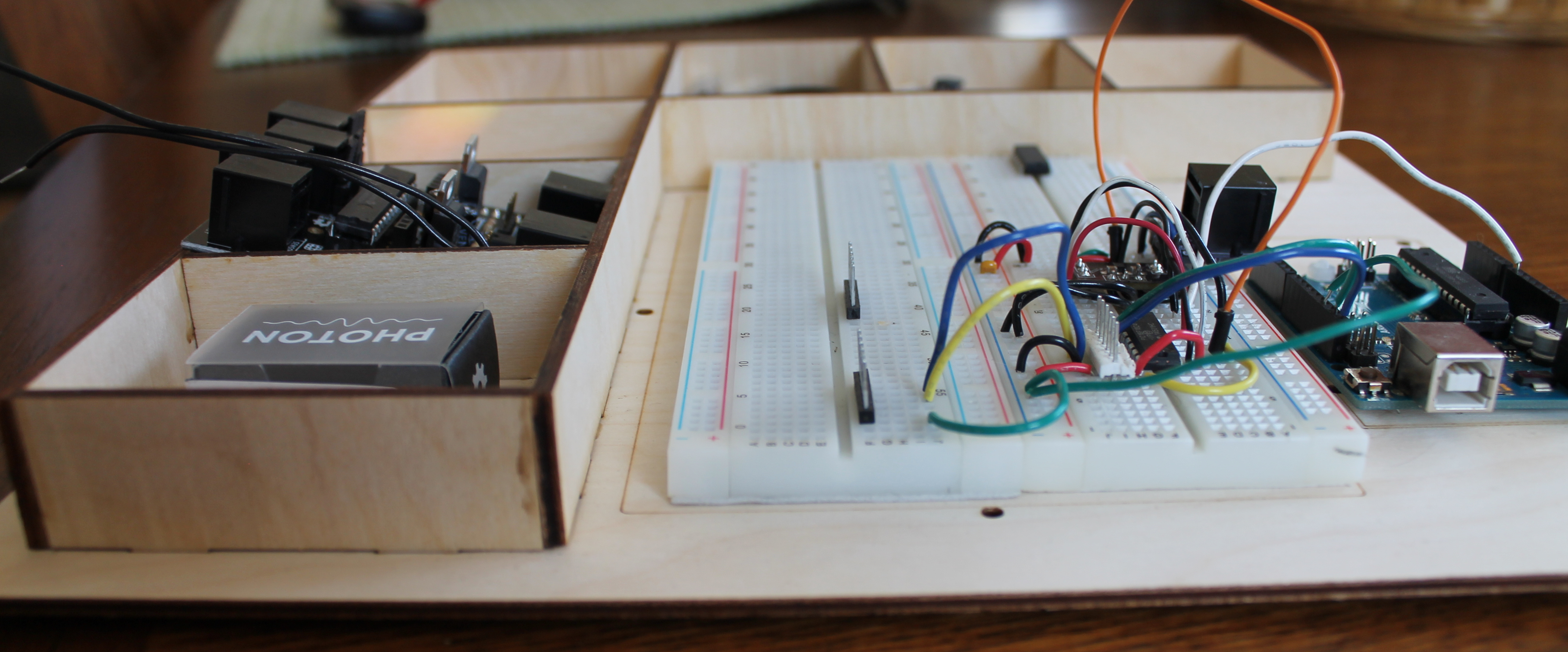
When I build electronics prototypes, it’s sometimes difficult to keep all the parts together without falling apart, especially if you need to move everything from one location to another. Between the breadboards, Arduino boards, programmers, FTDI cables, spare wires, and spare parts, I wanted to create a way to keep them all connected together without falling apart or losing anything.
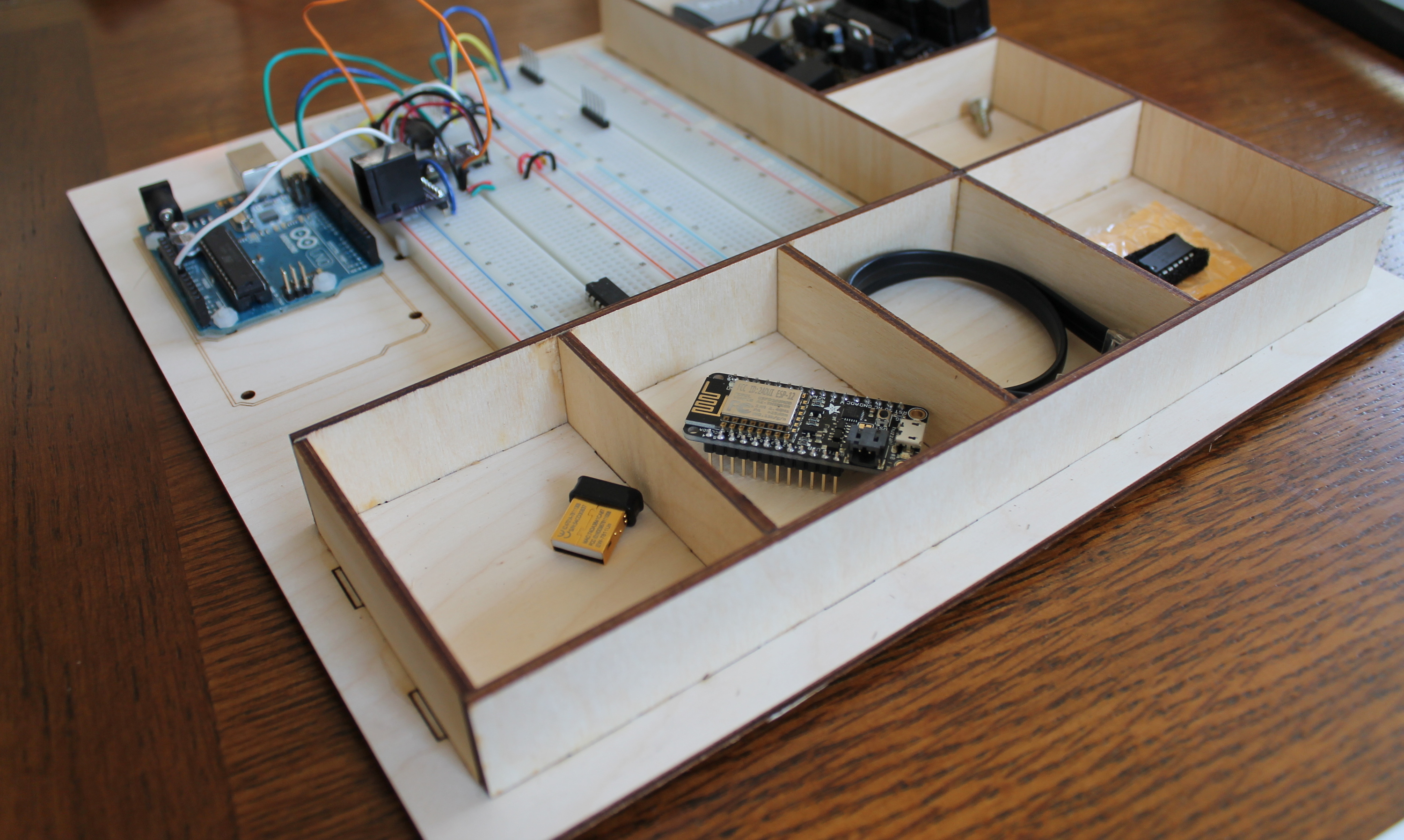
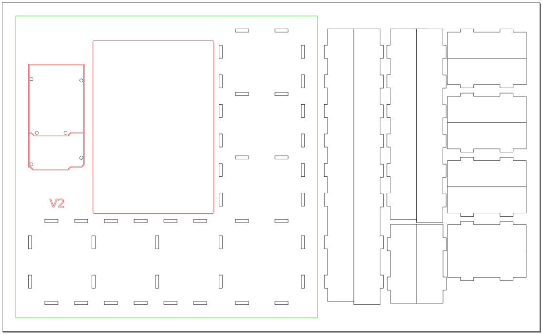
To this end, I designed a laser-cut Project Plate. It has holes for mounting an Arduino or Arduino Mega, a place for sticking a double-breadboard, and a series of customizable short boxes for holding parts.
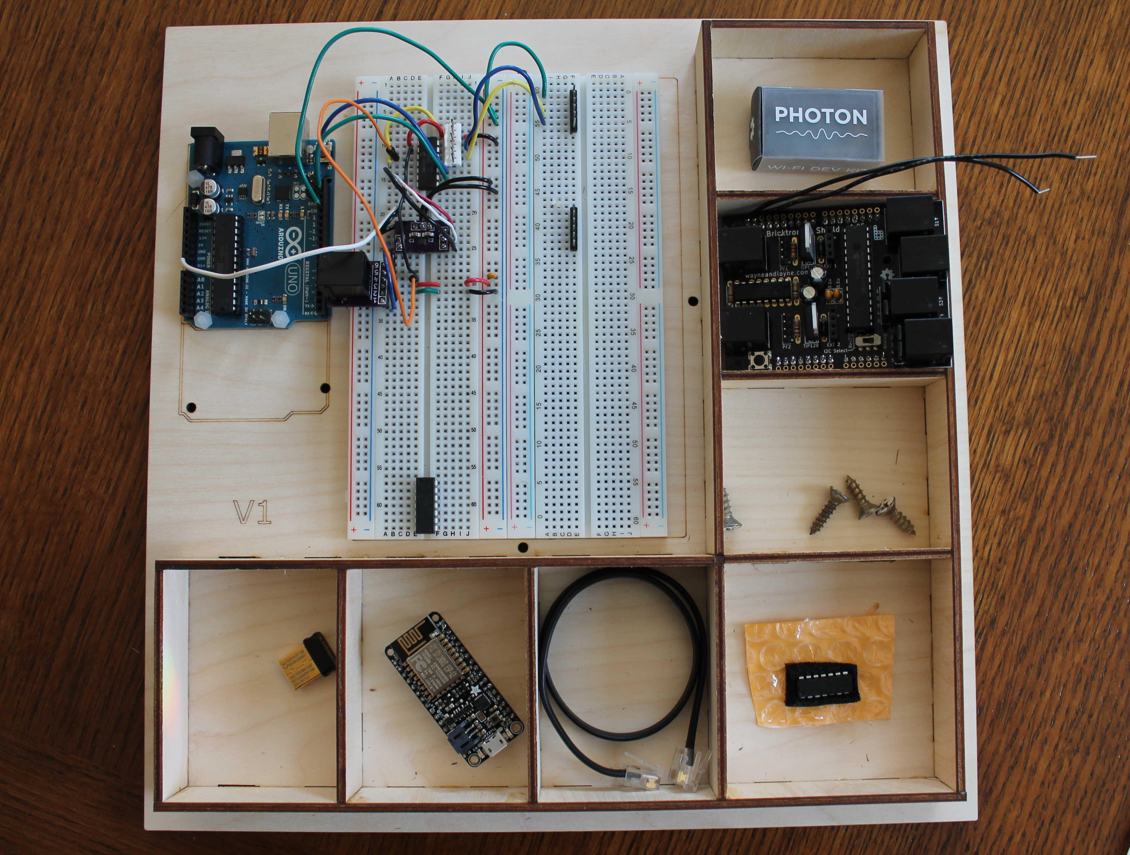
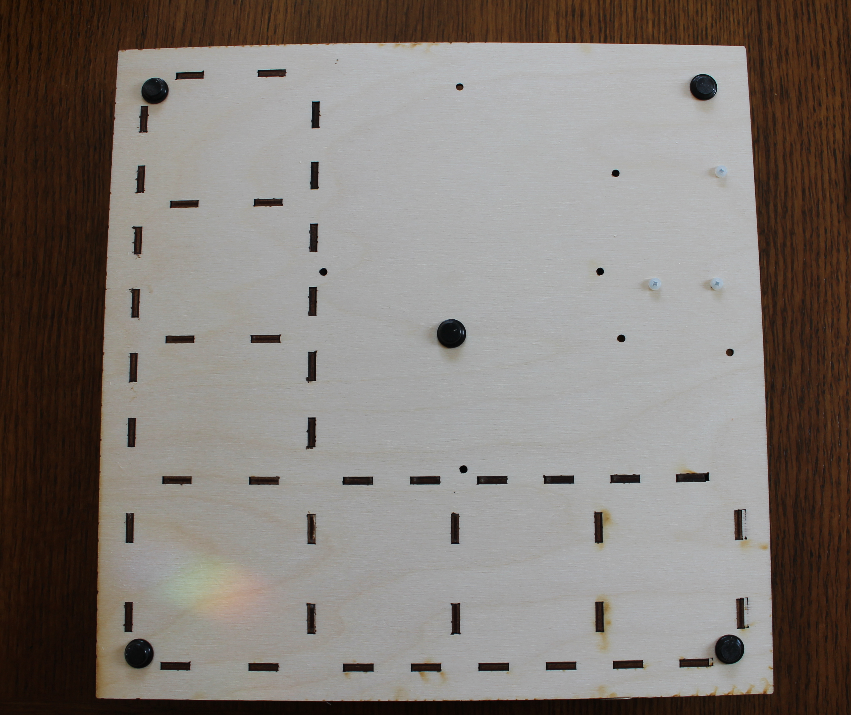
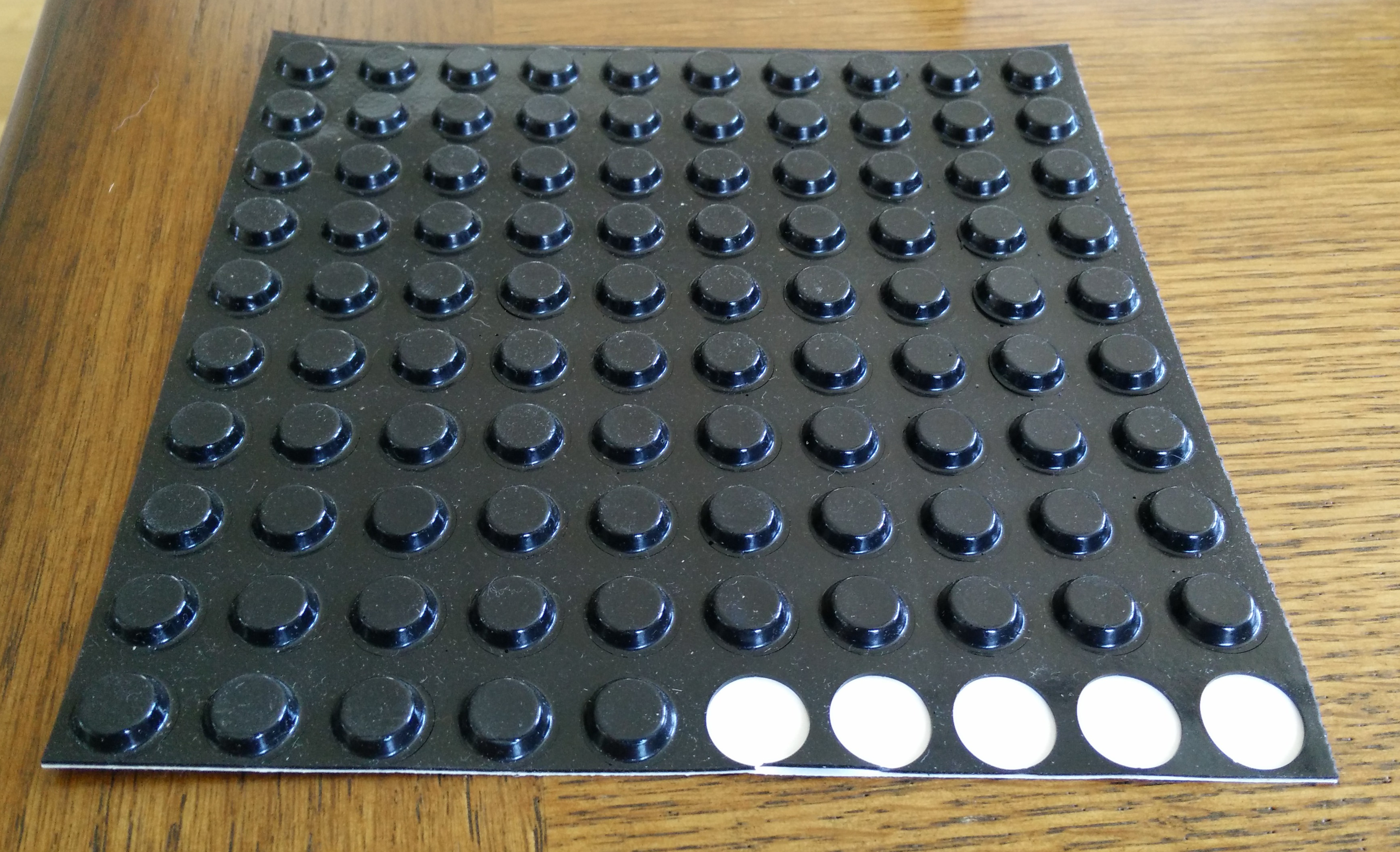
It took less than 15 minutes to cut on the laser cutter, and assembly took about an hour, plus time for the glue to dry. You don’t have to glue down all the box separators if you want to have larger boxes for longer wires or tools. With the arduino screws extending below the bottom of the plate, I added some adhesive rubber feet to the bottom to elevate it off the work surface.
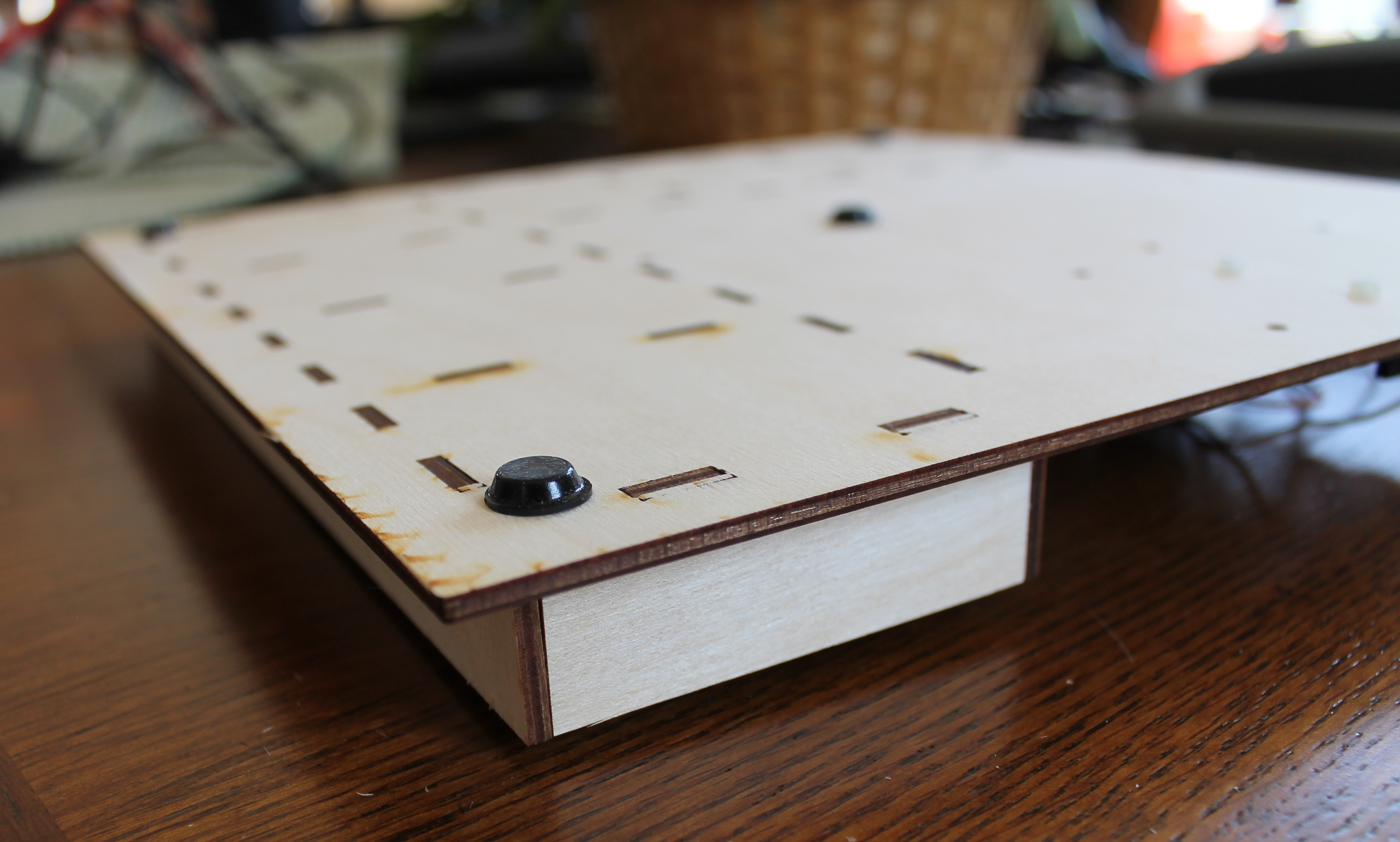
You can buy rubber feet like this on Amazon for dirt cheap.
If you want to cut your own, I have the SVG design file stored in the LaserCutProjectPlate repo at GitHub. I used 3mm (1/8″) baltic birch plywood and an 80W laser cutter.
Ideas for future improvements:
- Add a spot for a small USB hub?
- Add holes for mounting banana plug binding posts?
- Add a place to glue-down pass-through header pins for easier connections to chip programmers or FTDI cables?
Here are some additional photos: