


Design
Looking for the hardware design files? The schematics and much more is available at the download page.
Contents: POV Display — Charleplexing (GRID) Display — Bootloader — Pixel Messages — Font Table Messages — Message Format — Wrapping Messages — Blinky Data Transmission — Questions?
Persistence of Vision (POV) Display
The Blinky POV kit uses the persistence of vision effect to using a column of eight LEDs to simulate a 2D display. By rapidly flashing the LEDs on and off while waving the LEDs around in the air, a pattern of light can be “drawn” in the air:
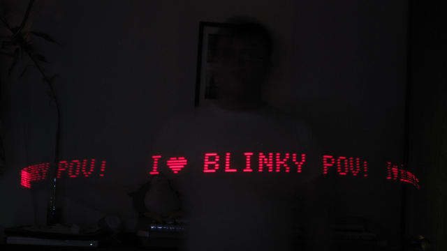
The microcontroller used in the Blinky POV kit uses eight general-purpose input-output pins to directly drive the eight LEDs for the POV display. The flashing rate is adjustable based on the values you specify in the blinky programmer.
Charlieplexing (GRID) Display
The Blinky GRID uses the same simple microcontroller to display messages and patterns, but uses many more LEDs (56, in fact) to show the message without needing to wave it around like the POV. To control so many LEDs with the few pins available on the microcontroller, we used a common technique known as “charlieplexing”. The name is a play on the word “multiplexing”, another common “pin sharing” technique used in electronics, along with the name of its originator, a guy named Charlie who worked at Maxim IC (a chip company).
Charlieplexing is used by a microcontroller to drive a large number of LEDs with a limited number of IO pins. The easiest way to understand the wiring diagram is to think of all the LEDs in pairs. Each pair of LEDs is controlled by two pins from the microcontroller. Because LEDs are diodes, they only light up when the electricity flows in a specific direction, and don’t do anything when the electricity is “backwards”. Each pair of LEDs are connected together backwards, so one LED’s positive lead is connected to the other’s negative lead, and vice-versa.
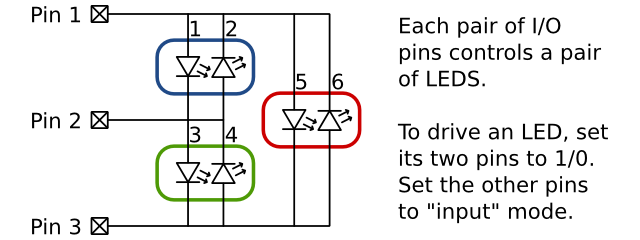
The diagram above shows a charlieplexing setup for using three IO pins to drive six LEDs. We have circled each pair of LEDs (three pairs). Notice that the blue pair is controlled by pins 1 and 2, the green pair is controlled by pins 2 and 3, and the red pair is controlled by pins 1 and 3. To turn on a specific LED, set the controlling pins to logic low / logic high (0 or 1) to get the LED to light up. For a charlieplexing circuit, we also need to set all the other pins to be inputs, instead of outputs.
On a modern microcontroller, each general-purpose input/output (GPIO) pin can be either an output or input pin. When a pin is in output mode, it drives the pin to either logic low (“ground” / 0 volts) or logic high (Vdd/Vcc, or the battery voltage). When a pin is in input mode, it doesn’t drive the pin to any particular value, and simply observes the value on the pin. This is similar to having a conversation with many people. It doesn’t really work out if everyone is shouting “HIGH!” and “LOW!” at the same time, nothing useful is accomplished.
There is more information on Charlieplexing at Wikipedia
Bootloader
The microcontroller used for the Blinky GRID and Blinky POV kits is a reprogrammable device. This means we write C language or assembly code on a computer, compile/assemble it, and program it into the microcontroller. While this works nicely for development, we wanted to allow people to update their messages without having to have any specialized equipment aside from a computer or smartphone. This requires us to be able to update the program information without using an actual programming device.
One popular method for updating the program code without a specialized programmer is a technique called bootloading, which utilizes two programs running on the same microcontroller. The first program is the bootloader itself, and is sort of like a start-up disk for your computer. The other program is the blinky program, which is the program that controls the LEDs and displays your messages. The main role of the bootloader is to update the blinky program and your stored messages. The main role of the blinky program is to read the messages from the EEPROM memory and display them on the LEDs.
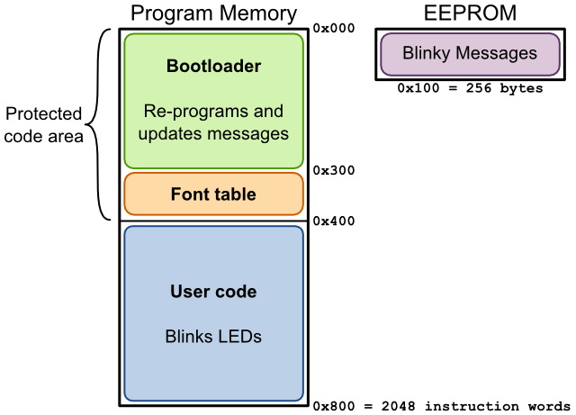
The diagram above shows a “map” of the program memory and EEPROM memory in our microcontroller. The program memory is shown on the left side, and is split into two sections. The top section is labeled “protected”, which simply means that it’s impossible to accidentally erase that section unless you have one of those specialized hardware programmers. We use this protected region to store our bootloader and the font table (more about the font table below). The second half of the program memory is not protected, and we store the blinky code there. This allows us to update the blinky code without a specialized hardware programmer.
The EEPROM memory shown on the right side of the drawing is used to store all the blinky messages for display. It can store 256 bytes, which should be more than enough for any complicated messages. The bootloader receives data from the computer/smartphone and updates the values stored in the EEPROM. This is how you can change the display messages on your Blinky POV or Blinky GRID.
Pixel-Based Messages
There are two types of message you can display with your Blinky kit. The first type is called a pixel-based message, because you get to specify the message down to the pixel. For example, if you wanted to display the message “hello world” using a pixel-based message, it might look something like the following image:
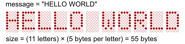
We have highlighted LED “pixels” in the above image to spell out our message. With 11 letters in the message, and five columns per letter, this message requires transmitting and storing 55 bytes of data. Compared to the font-based message (discussed in the next section) this is a lot of bytes to transmit and store in the Blinky. One advantage of using pixel-based messages is that you can create any design you can think of, with no restrictions (aside from storage space, of course). One cool use for pixel-based messages would be to create custom letters or other characters that aren’t included in the font table, such as a smiley face or special characters.
Font Table-Based Messages
As mentioned above, there are two types of messages you can use with your Blinky: pixel- and font-based. Font-based messages don’t transmit the raw pixel data for each letter, they simply use a code for each letter, saving space and transmission time. The font table is stored in “protected” memory in the Blinky chip, so it can’t be accidentally deleted while updating your messages or program.
The “hello world” example is continued in the drawing below. The full font table is also shown, containing the usual letters and numerals, as well as period, exclamation mark, ampersand, comma, and space.

Each letter in the font-based message is translated into a single byte, instead of five bytes per letter as in the pixel message above, a savings of 80% in storage and transmission time. The only downside to this space savings is that you are restricted to the characters we included in the font table.
One way to work around this restriction is to use multiple messages. For example, if you wanted to display the message “I heart Mom!”, but with an actual heart instead of the word “heart”, you could use three messages. The first message would be a text-based message of “I “, the second message would be a pixel-based drawing of a heart symbol, and the third message would be a font-based message that said ” Mom!”.
Message Format
Once you have created a message, either pixel- or font-based, there is a little bit of extra information we need to store with the message, so the Blinky knows how to display it. The message data bytes are stored in the Blinky kit with two extra bytes of information, as shown in the top drawing below. The first extra byte stores configuration information for the message, while the second extra byte stores the number of data bytes in the message.
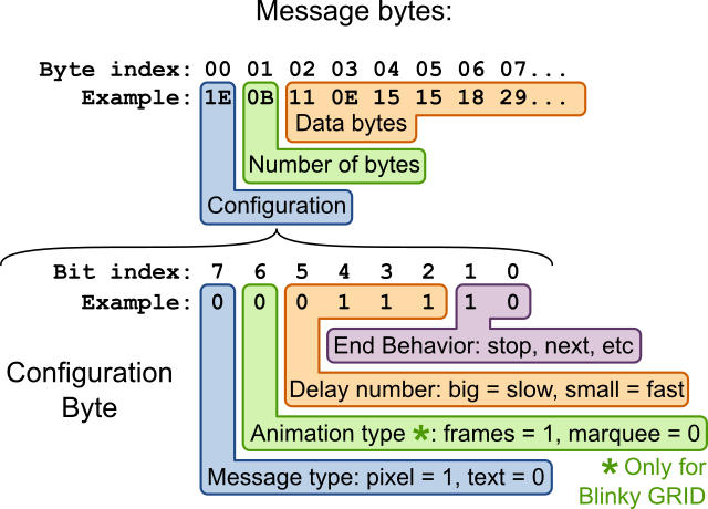
While the number of bytes in a message is straightforward, the configuration byte requires a bit more explanation. The eight bits of the config byte are allocated to four message settings. The most significant configuration bit (bit 7 in the drawing above) tells the blinky whether the message is a pixel- or font-based message. Bit 6 indicates whether a pixel-based message should be shown one “frame” at a time, or whether it should be a scrolling marquee. This only applies to Blinky GRID devices.
The middle four bits are collected together into a four-bit binary number with a range of 0 to 15. This number is the delay number, where a big value makes for a slow message playback, and a small value makes for a fast message playback. The final two least-significant bits select one of four possible end behaviors. This controls what the Blinky does after it finishes playing a message. The possible end behaviors are “Stop”, “Repeat this message”, “Advance to next message”, and a special “Easter Egg” option. Can you find the secret behavior?
Use the same technique for all messages you want to transmit to the Blinky, and put all the messages bytes together in a long string of bytes. Then, count up the number of messages, and put that number as the very first byte. This tells the Blinky chip how many messages to read from the internal memory. This is a diagram of how it will look when stored in the “Electronically Erasable Programmable Read Only Memory” (EEPROM) inside the Blinky chip.
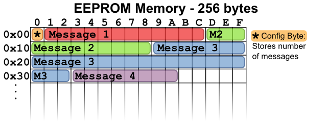
The above diagram shows the EEPROM memory with four example messages stored. The first byte of EEPROM memory is a configuration byte, which stores the number of messages. In this example drawing, the config byte would contain the number 4, because there are four messages stored in the device.
Wrapping up the messages for transmission
Once the messages have been created (see previous section), we need to prepare them for transmission to the Blinky device. This involves wrapping them up into records, which enables more reliable transmission. In the world of microcontrollers and microprocessors, there are a few common file formats for storing the raw binary data to transmit to a processor. One very popular file format is the Intel HEX file format, shown in the diagram below. It consists of a number of records, one per line in the file.
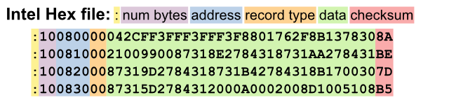
Each record starts with a colon (:), and is followed by a variety of data fields. All values are stored as ascii-encoded hex values. For example, the four records shown above all have 16 bytes of data. In hexadecimal (base-16 numbers), the number 16 is expressed as 10 or 0x10 (the 0x indicates the number is a hexadecimal number), so we store the value 10 in the “num bytes” field for each record. The address field is two bytes that say where to store the data, and the record type field indicates the record type (naturally), with type 0 being a standard data record. The checksum field is used to help prevent programming errors.
We are using a slightly-modified version of this file format for blinky transmission to the Blinky POV/GRID kits. There are a number of small changes:
- We don’t transmit the initial : in each record.
- In the standard hex file, a value such as 16 is encoded in hex as “10”, and then transmitted as two ASCII bytes “1” and “0”. This encoding is beneficial for serial-port transmission (it only uses printable ascii characters 0-9, A-F, ‘:’) but actually is half as fast as non-encoded transmission, because the 1-byte value “16” ends up requiring the transmission of two bytes (“1”, “0”). We transmit the raw binary values, instead of hex-ASCII encoding them first, to make transmissions quicker.
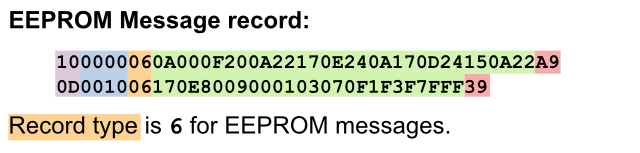
- We added a new record type, with value 6. This record type is used to transmit records to update the EEPROM memory for changing the stored messages.
Blinky Data Transmission
Once we have wrapped up all our messages into modified Intel HEX records, we are ready to transmit the data to the blinky device. We are utilizing a neat visual transmission scheme, that uses two blinking squares on a computer/smartphone screen to transmit data to two light sensors on the blinky device.
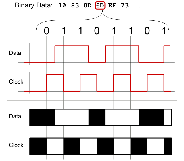
The above diagram shows how we prepare the binary data values for transmission. First, we look at the binary value of each byte. For example, the hex value 0x6D is binary 01101101. We are using a “data and clock” transmission scheme, where the data value is sampled when the clock changes. To transmit the eight bits in 0x6D, we need eight clock transitions, shown in the drawing above. At each of these eight clock transitions, we must pre-set the data value to be the correct binary value (0 or 1). To transmit a 0 value, we must set the data line to 0 before the next clock transition. See if you can recognize the zeros and ones transmitted by the red lines above. Notice how the data value only changes between clock transitions. To translate the red lines into black and white flashing squares, we simply assign 0 = black and 1 = white. This sequence of black and white is then reproduced on the computer or smartphone screen of our programming webpage.
Questions?
So yeah, there’s a lot going on in these little kits, and I’m sure we forgot something or glossed-over some important detail. We take great pride in our design documentation, and would love to get your feedback! Feel free to post in the Wayne and Layne forum, or contact us privately if the forums just won’t do.