


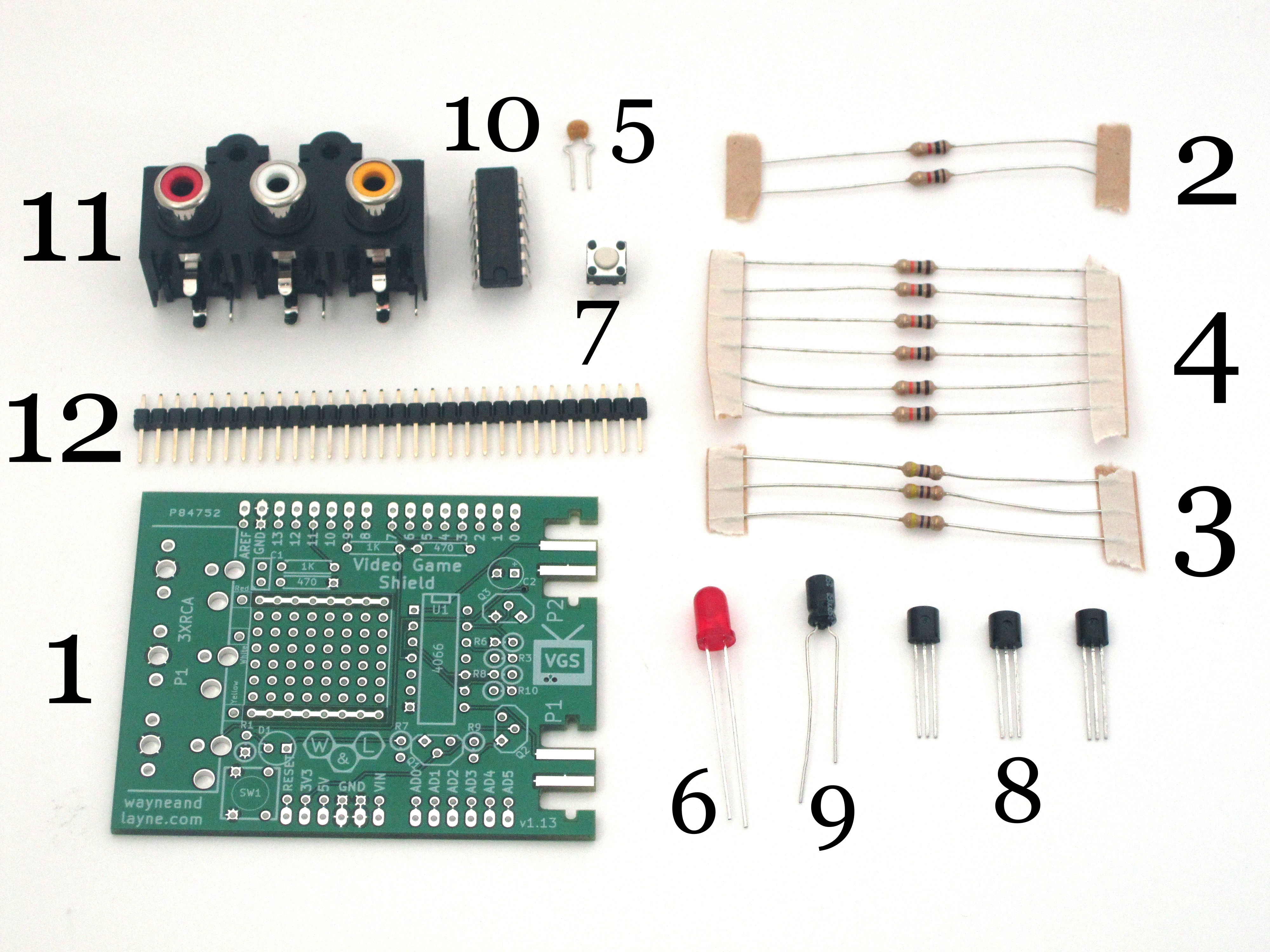
Parts List
- (1) Video Game Shield Printed Circuit Board – PCB
- (2) 1 kΩ resistors – R4, R11
- (3) 470 Ω Resistor – R1, R5, R12
- (6) 10 kΩ resistors – R3, R6, R7, R8, R9, R10
- (1) .1uF Ceramic Capacitor – C1
- (1) LED – D1
- (1) Push button – SW1
- (3) N-channel MOSFETs – Q1, Q2, Q3
- (1) 47 uF Electrolytic Capacitor – C2
- (1) 4066 Quad Analog Bidirectional Switch and Chip Socket – U1
- (1) Red/White/Yellow RCA connector – P1
- (1) Breakaway male headers
What does each part do?
There’s more information about the design of the Video Game Shield kit at the Design page.
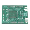
Video Game Shield PCB (Back to list)
The Video Game Shield PCB is a professionally made printed circuit board with soldermask for easy soldering and silkscreen printing for easy assembly. The board has been designed with breakout holes and places to cut individual traces for easy modification. There’s a small prototyping area with the standard 0.1″ hole spacing. The top and bottom rows are electrically connected. The right side of the PCB consists of cutouts. These cutouts are the connectors for the Nunchuck. Anything that can plug into the bottom of the Wii Remote can connect to these cutouts, such as the Classic Controller or the Wii Motion Plus (Wii Motion Plus is not yet supported). Because of the notches, the Nunchuck connector “snaps in” to the board.
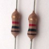
The resistors are used for a variety of purposes in the Video Game Shield. They allow the microcontroller to create the proper analog voltages for black and white television, as well as scale the audio waveform for line-in output to a TV. They act as pull ups for the I2C communications with the Nunchucks, as well as make the inverter work to properly select between the two Nunchucks. There’s more information about each of these uses at the Design page.
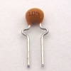
0.1 uF Ceramic Capacitor (Back to list)
The 0.1 uF ceramic capacitor is used to block the DC component of the audio signal from the input to the television. The AC component, the “audio signal” passes through, but the large signal DC component is blocked.
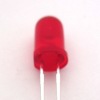
The LED is used as a power indicator. When the board is powered, the LED lights up. It is a standard 5mm (T1-3/4) LED package.
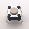
The push button acts the same as the reset button on the Arduino board. The specific pushbutton we use is the B3F-1000 by Omron Electronics.
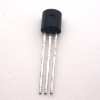
N-channel MOSFETs (Back to list)
Q1 is used as an inverter, maintaining the enable lines of the 4066 IC. Q2 and Q3 are used to interface the 3.3 V Nunchuck signals with the 5 V Arduino. There’s more information about each of these uses at the Design page. The specific transistor we use is the standard 2N7000, such as this one.
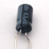
47 uF Electrolytic Capacitor (Back to list)
When a nunchuck is connected or disconnected, it can create a voltage draw that can overwhelm the Arduino power supply. The 47 uF electrolytic capacitor helps smooth out the spikes and prevent problems. Any 10-100uF electrolytic capacitor should work, but we use this 47uF, 16v capacitor.
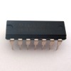
4066 Quad Analog Bidirectional Switch (Back to list)
The 4066 IC is a quad bidirectional analog switch. This means there are 4 pairs of pins which act like they are either electrically connected or not electrically connected, depending on the voltages on each pair’s respective enable pin. It’s used to switch between the two Nunchucks which have identical I2C addresses. Like all of the 7400-series and 4000-series logic chips, there are a lot of different variants offered by each manufacturer. The specific 4066 chip we use is the SN74AHC4066N from Texas Instruments.
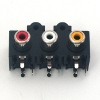
Red/White/Yellow RCA connector (Back to list)
The RCA connector is used to connect the PCB to the proper cables used for connecting to the television. They are color coded. The yellow cable is for video signal, and the white and red are for the two channels of audio. On this shield, both of those are connected together, but the PCB has been designed so it’s easy to cut a trace and add a wire to enable stereo audio. There are a ton of different 3xRCA jacks out there, but this is the specific 3xRCA jack we use for the Video Game Shield. It’s also called the Krycon klp-843g3-rwy-def.
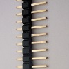
Breakaway male headers (Back to list)
Male headers are used to connect the shield to the Arduino. They come in long strips and are broken into the appropriate lengths.