


Use
While the Tap-Tempo Metronome isn’t meant to require a thorough review of any instructions, some subtle features have been added that may not be easy to discover.
To begin to use the Tap-Tempo Metronome, slide the power switch to the position labeled “on” on the PCB. If the up button is pressed when the power is turned on, the pitch will be set higher. If no buttons are pushed when the power is applied, the beep will be at its loudest, at a midrange pitch. If the down button is pressed, the pitch will be set lower.
There’s no pattern set, so the display shows the word “tap” and the device is ready to record a pattern. Any taps to the black circular speaker element are recorded. Any pattern needs to be repeated a minimum of three times. The display flashes brighter when the device detects a tap.
When you’re done entering the pattern, either wait a few seconds for the recording to time out, or press one of the buttons. This will end the recording. The Tap-Tempo Metronome calculates an average pattern and plays it back. If the pattern is a metronomic tapping, the display will show the beats per minute. If the pattern is more complex than a simple metronome beat, the total “patterns” per minute of the entire pattern will be displayed.
During playback, the up and down buttons adjust tempo. This is immediately reflected in both the audio and on the display. If you hold the up and down buttons, they will repeatedly trigger, allowing quick changes to tempo.
To reenter recording mode, tap the Tap-Tempo Metronome in between beeps. When you’re finished playing with the Tap-Tempo Metronome, it can be turned off with the power switch.
Advanced Usage
To make your metronome even more fun, you can connect it to external actuators and sensors. Want to make your metronome even more tactile? Try attaching a vibration motor so you can feel each beat. You can also connect your metronome to a motor or solenoid to activate other instruments, such as beating a drum!
Troubleshooting
If your Tap-Tempo Metronome used to work, and no longer functions properly, try changing the batteries.
If the display doesn’t light up when you turn on your Tap-Tempo Metronome, shut it off and make sure the batteries aren’t backwards.
If your Tap-Tempo Metronome isn’t picking up your taps:
- Try tapping with your fingernail instead of the pad of your finger.
- Try tapping with a pencil.
- Try gently tapping the entire unit against a table or other hard surface.
If your Tap-Tempo Metronome isn’t picking up your pattern correctly, but is picking up your taps:
- Make sure every tap is being picked up. Without every tap, the software cannot determine the proper length of your pattern.
- Repeat the pattern more than three times.
- The metronome averages out the taps to determine the pattern, so try varying the speed of your taps until the metronome recognizes the pattern, and then make any required tempo changes with the adjustment buttons.
If you have further difficulties, please contact us.
Advanced Troubleshooting
If the display doesn’t light up when you slide the power switch to “on”, we can check the power supply with a multimeter.
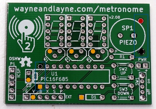
- First, make sure the batteries are installed correctly and slide the power switch to “off”. Using the voltage mode on your multimeter, measure the voltage between the terminals of the battery holder, on the right side of the circuit board. Connect the black lead to the lower terminal (marked in black on the image) and connect the red lead to the upper terminal (marked in red on the image). This should measure the voltage of the three batteries in series, and the multimeter should read between 3 and 4.5 volts. If this is not the case, you might try fresh batteries.
- Next, slide the power switch to “on”. Keep the black lead on the ground pin, and move the red lead to the upper terminal of the power switch, marked in orange on the image above. If the switch is “on” it should be the same as the battery voltage.
- Then, measure the voltage at each of the orange points, moving in a counter-clockwise direction. If the power switch is “on” these should all be at the battery voltage.
- Finally, measure the voltage across the chip, at pins 1 and 20 on the left side of the chip, marked in orange and black in the image above. This should be the same voltage as the batteries.