


Build Instructions
Looking for shorter instructions? Look no further. We’ve prepared a shorter page with the suggested soldering order.
Have an older kit? These instructions are for the current TM2 kit. If you happen to have one of the original kits, we’ve archived the build instructions.
Step 0: Gather Tools
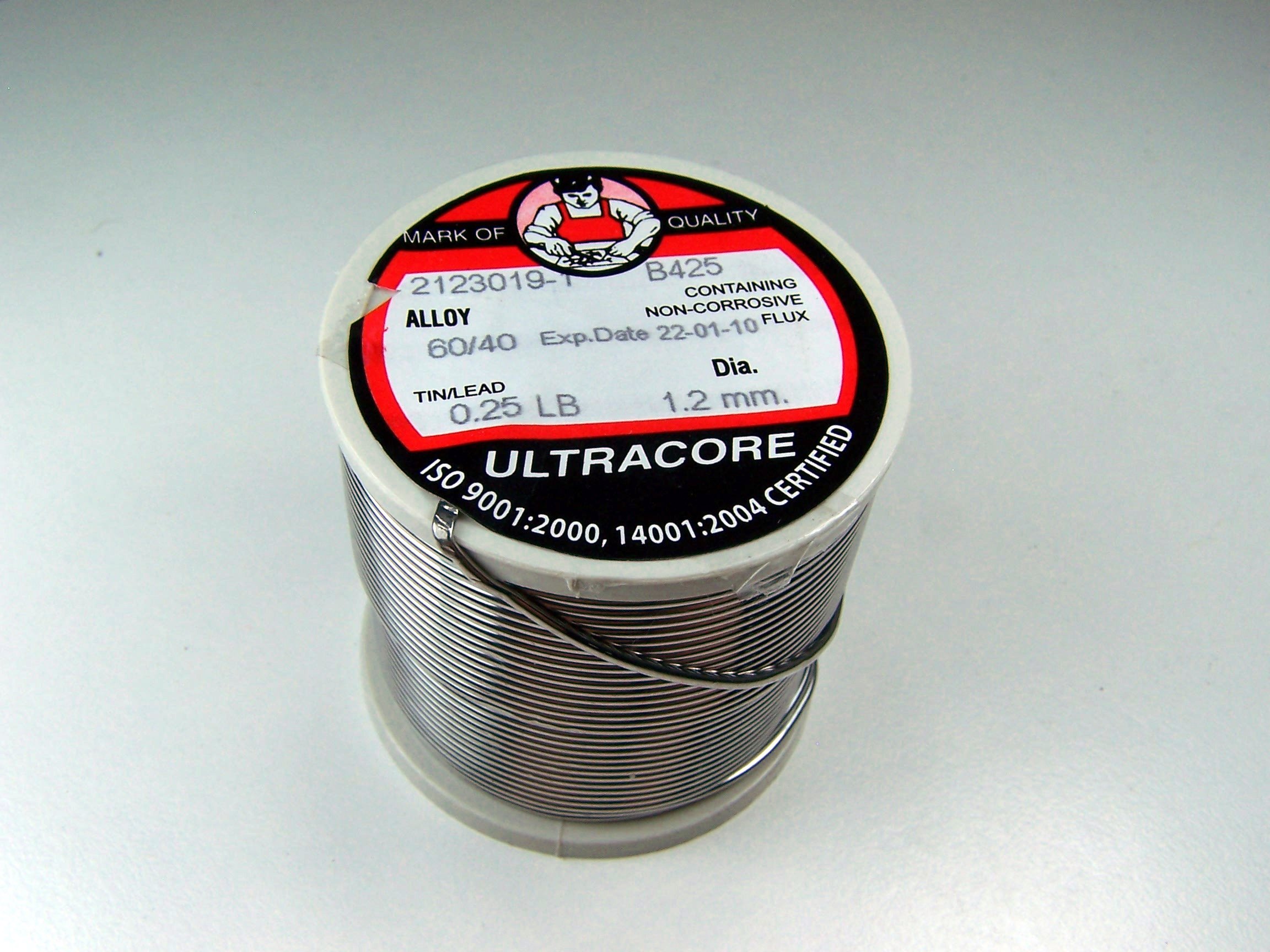
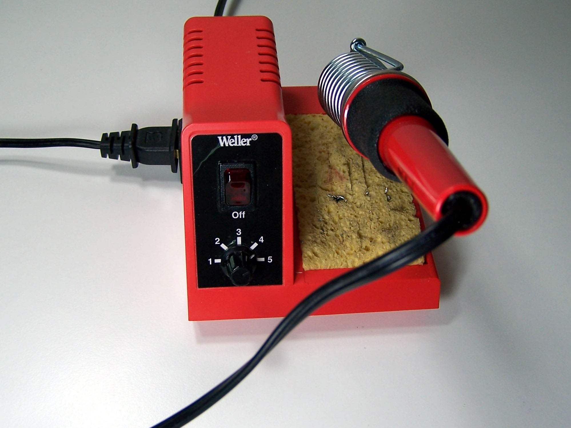
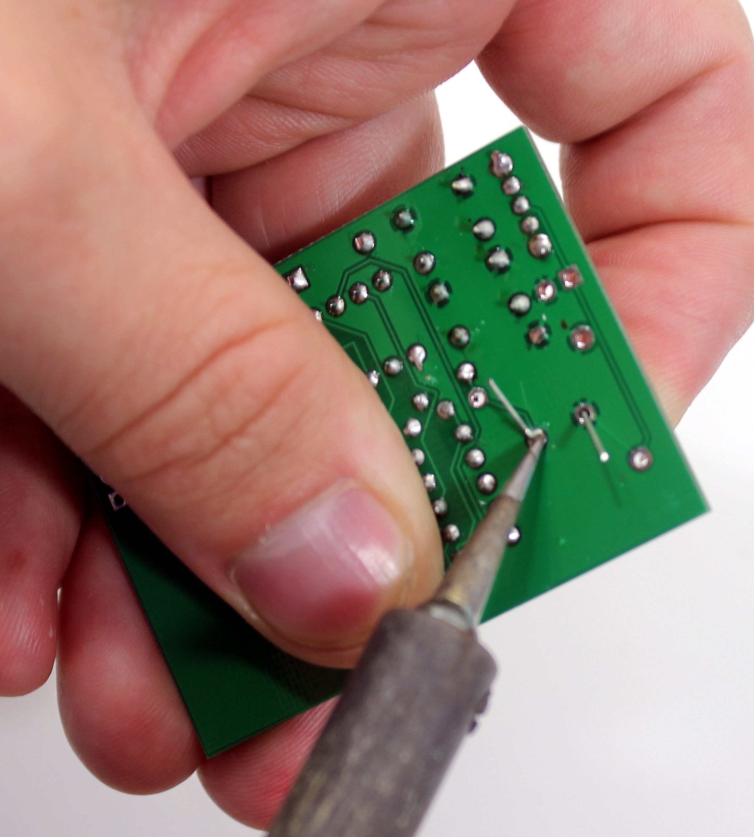
To build the Tap-Tempo Metronome, you will need a few common tools for soldering and electronics work. A soldering iron and solder are the most important tools. You can use any soldering iron, although a higher-quality, temperature-controlled adjustable iron will be easier to work with and give higher quality results. Any standard solder for small electronics will do just fine.
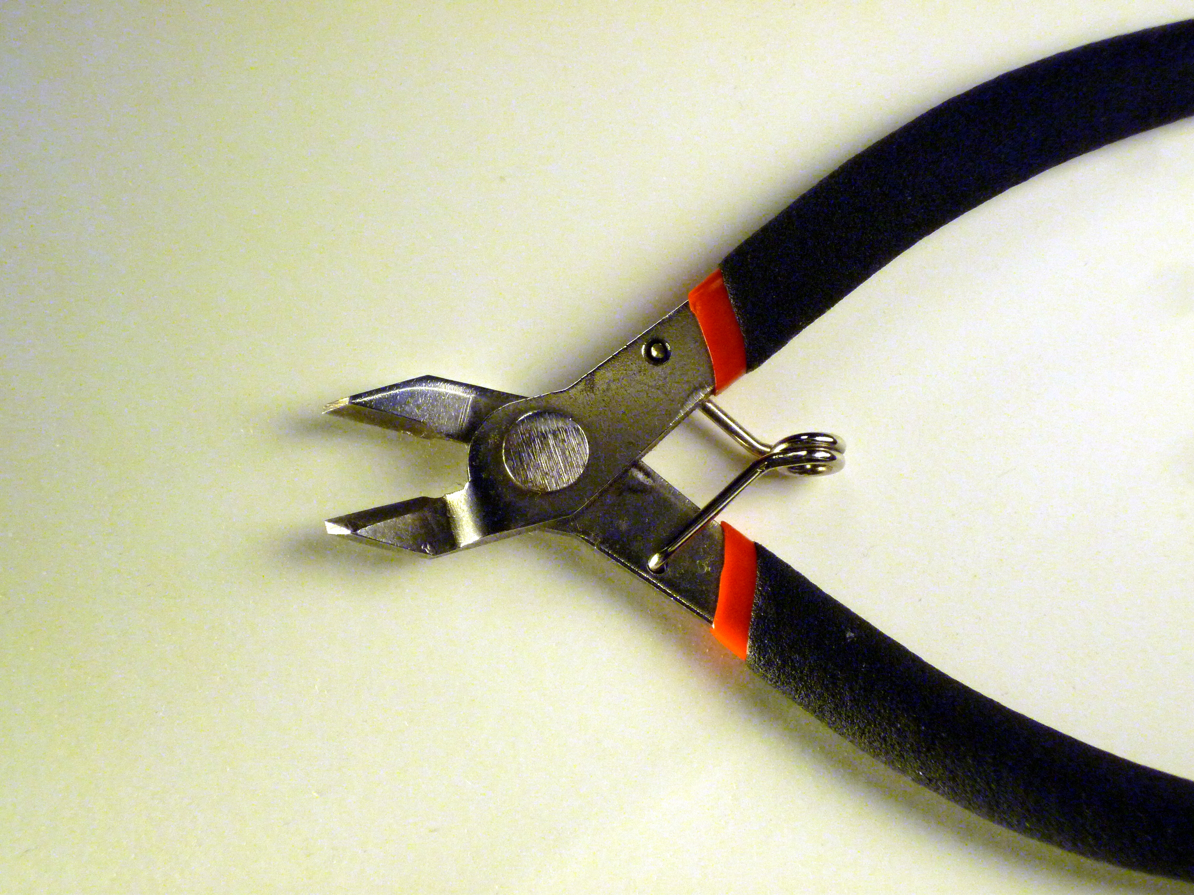
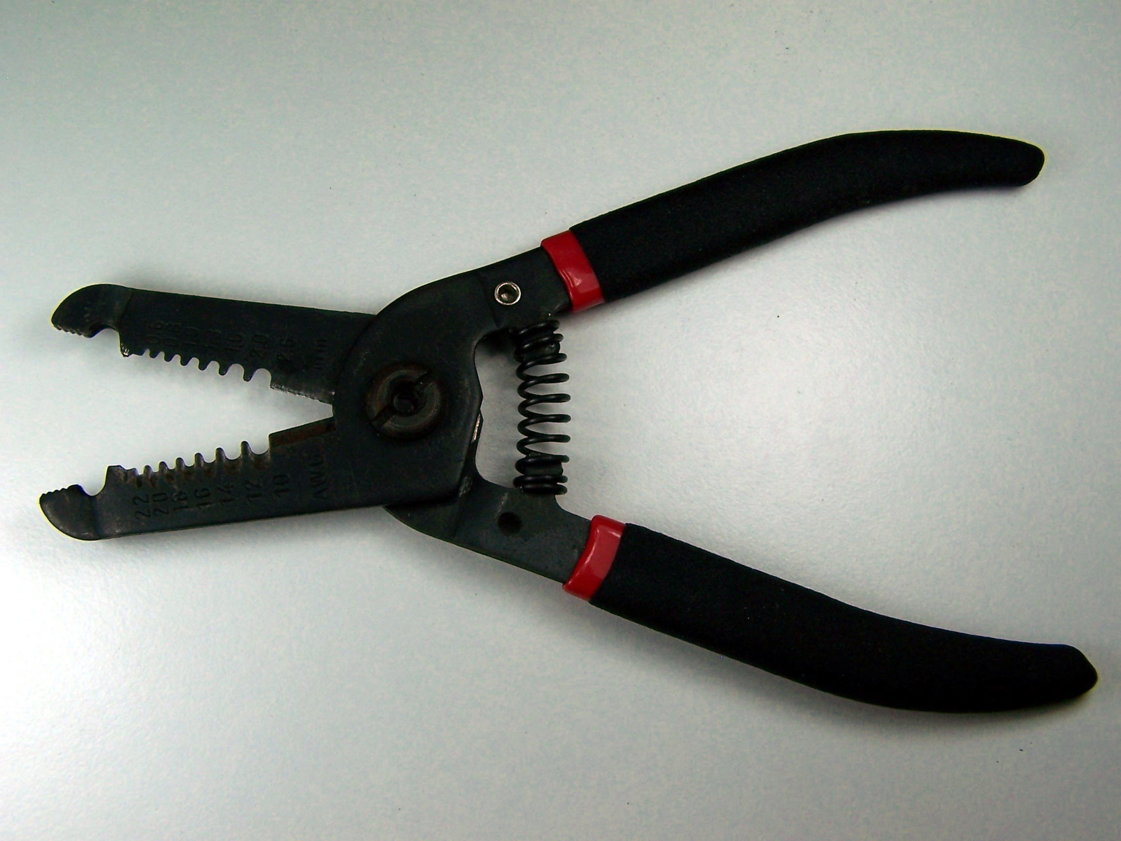
To bend the leads of the push buttons, you will need a pliers or similar tool. We used the pliers on a wire strippers. To trim the extra leads on the bottom of the pcb a diagonal pliers will work very well.
If you need some additional guidance and instruction on soldering, SparkFun, NASA, and Curious Inventor all have quality soldering tutorials.
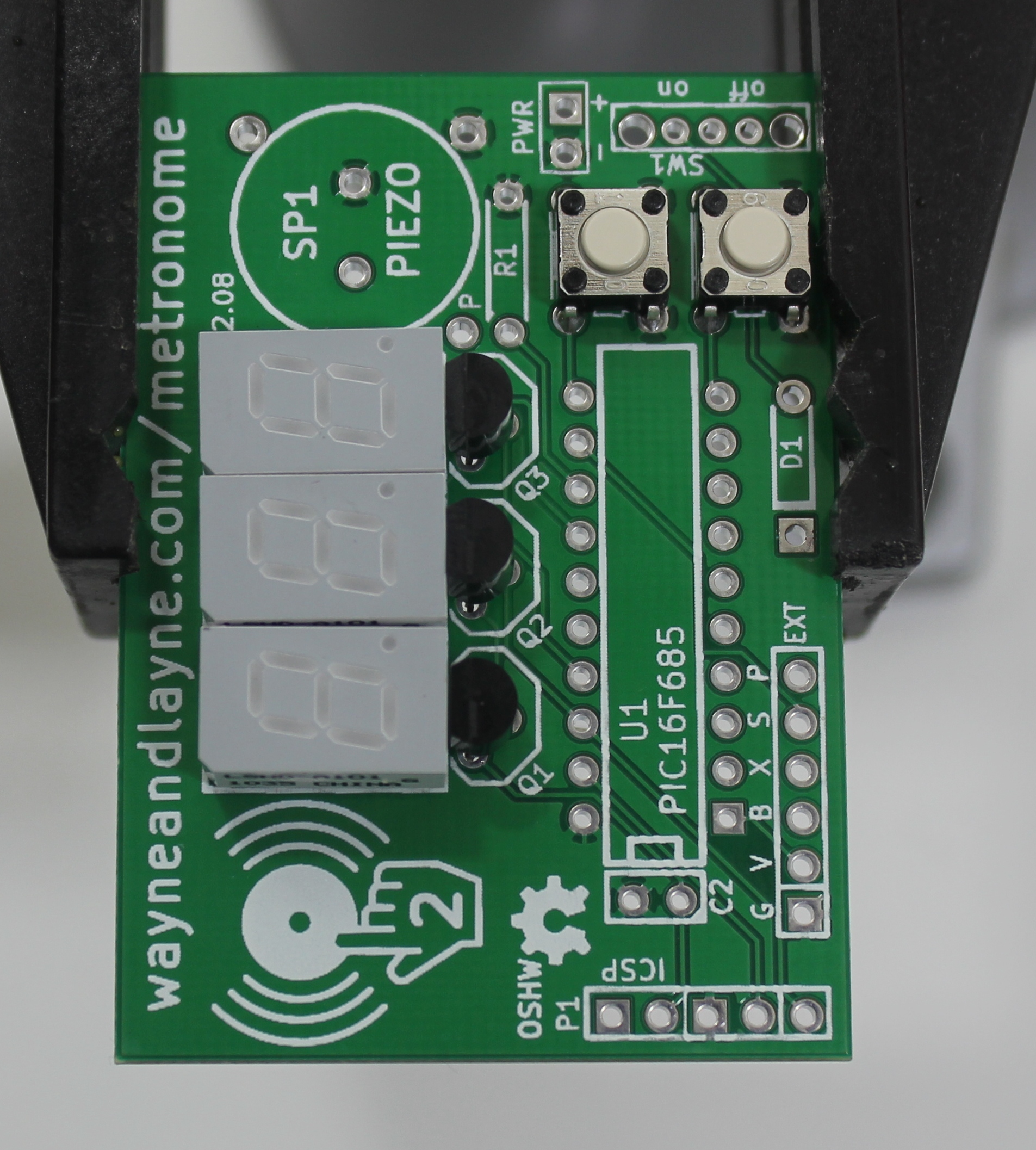
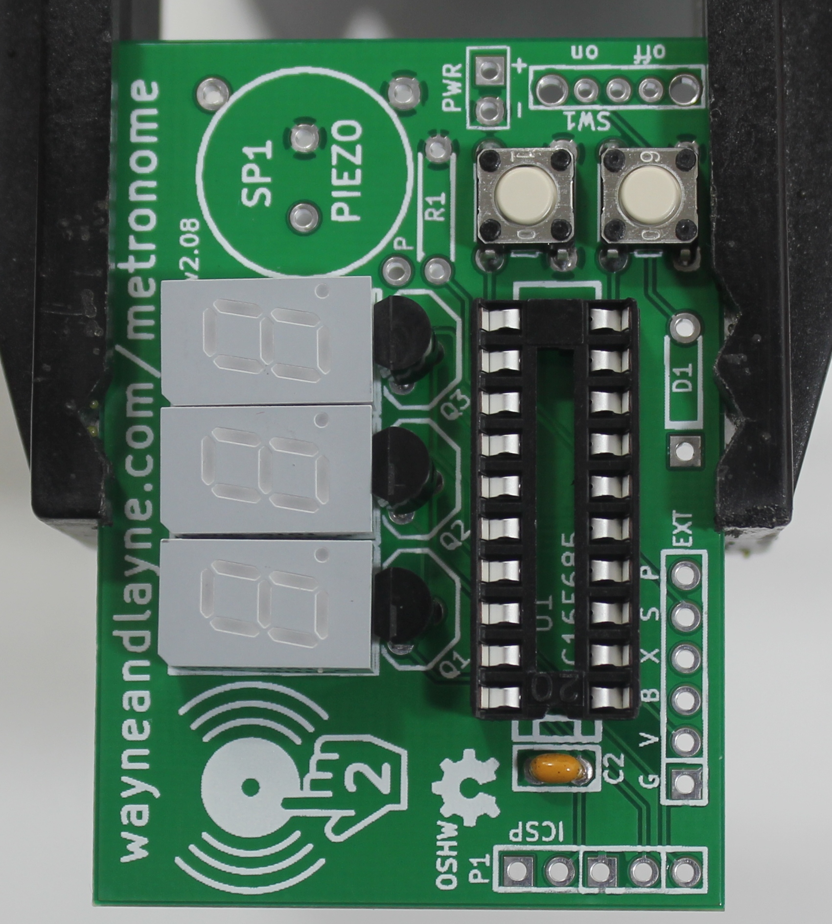
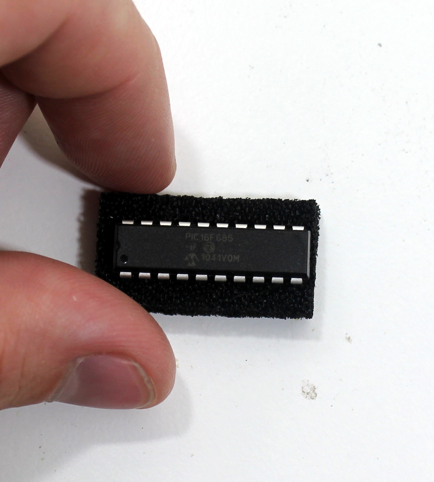
Step 1: Part Identification
Open the bag of parts, and make sure you have all of the parts listed below. It might be easier to lay them out as shown in the picture. Click to enlarge.
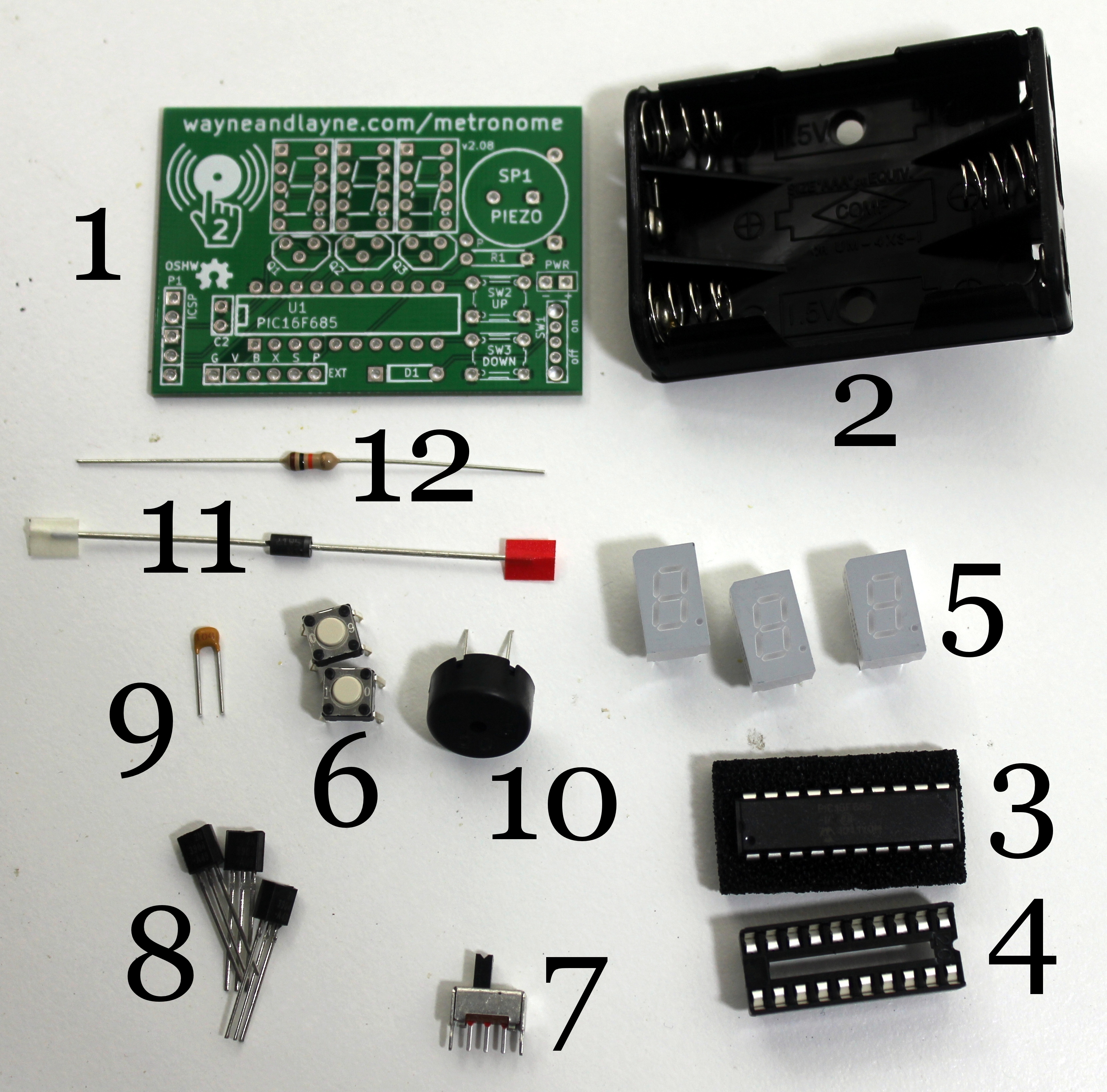
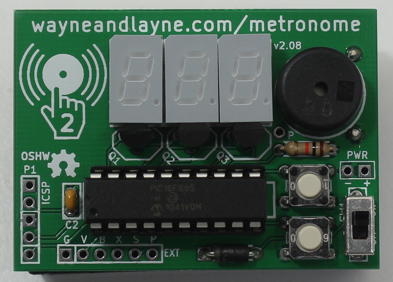
- (1) Tap-Tempo Metronome PCB
- (1) 3 AAA Battery Holder
- (1) PIC16F685 Microcontroller
- (1) 20 Pin DIP Socket
- (3) Seven Segment LED Displays
- (2) Push Buttons
- (1) Power Switch
- (3) NPN Transistors
- (1) 0.10 uF Ceramic Capacitor
- (1) Piezo Speaker
- (1) Power Protection Diode
- (1) 10 kΩ Resistor
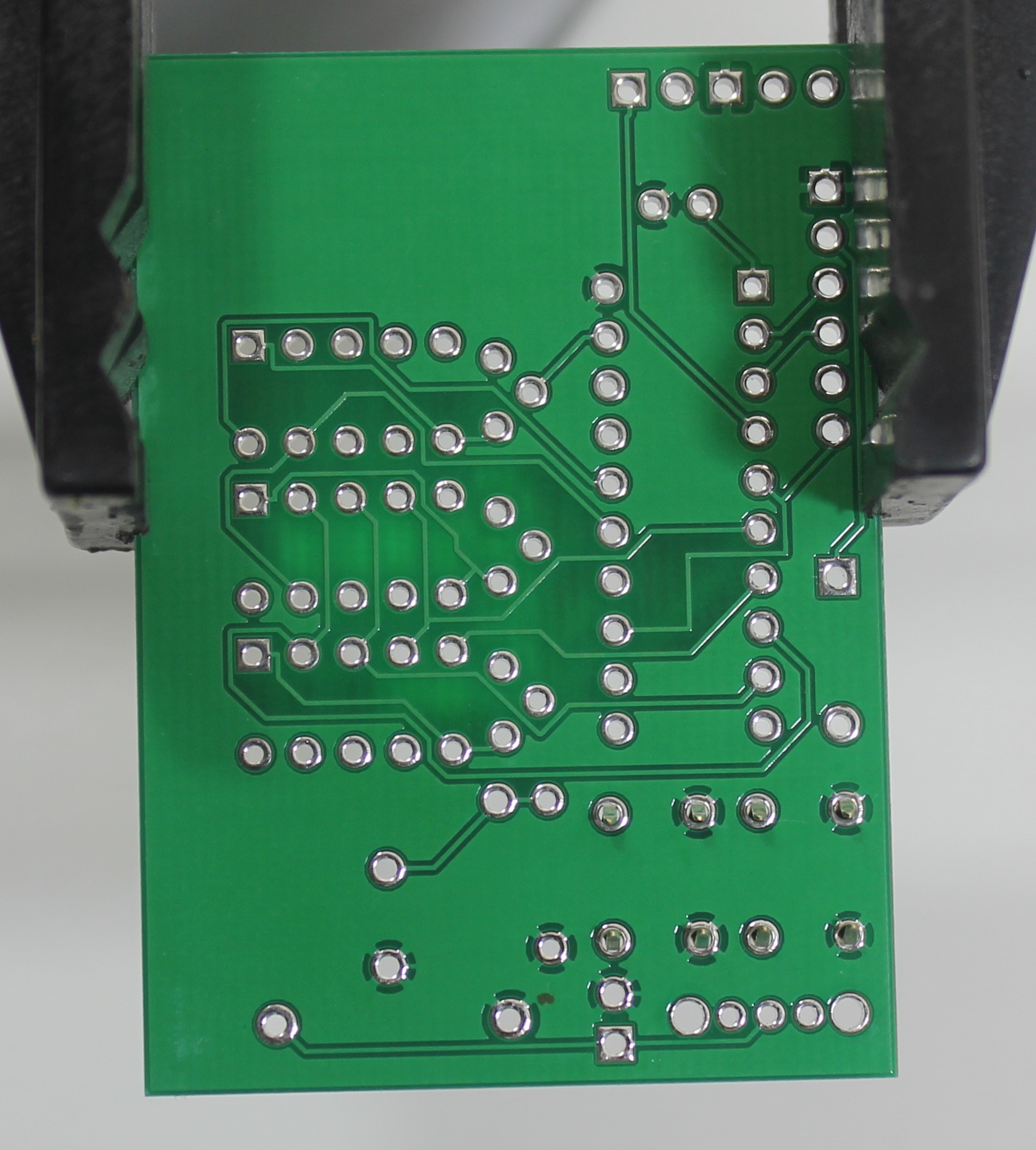
This kit is easy to solder. However, the seven segment displays can be a little tricky to get properly aligned. The alignment is made much easier if the assembly can be set on a flat surface while the seven segment displays are being soldered. To do this, we’ll make sure to only solder parts that are shorter than the displays before getting to the displays. This will also give you a chance to practice your soldering on some easier parts with pins that are more spread apart, before getting to the trickier displays.
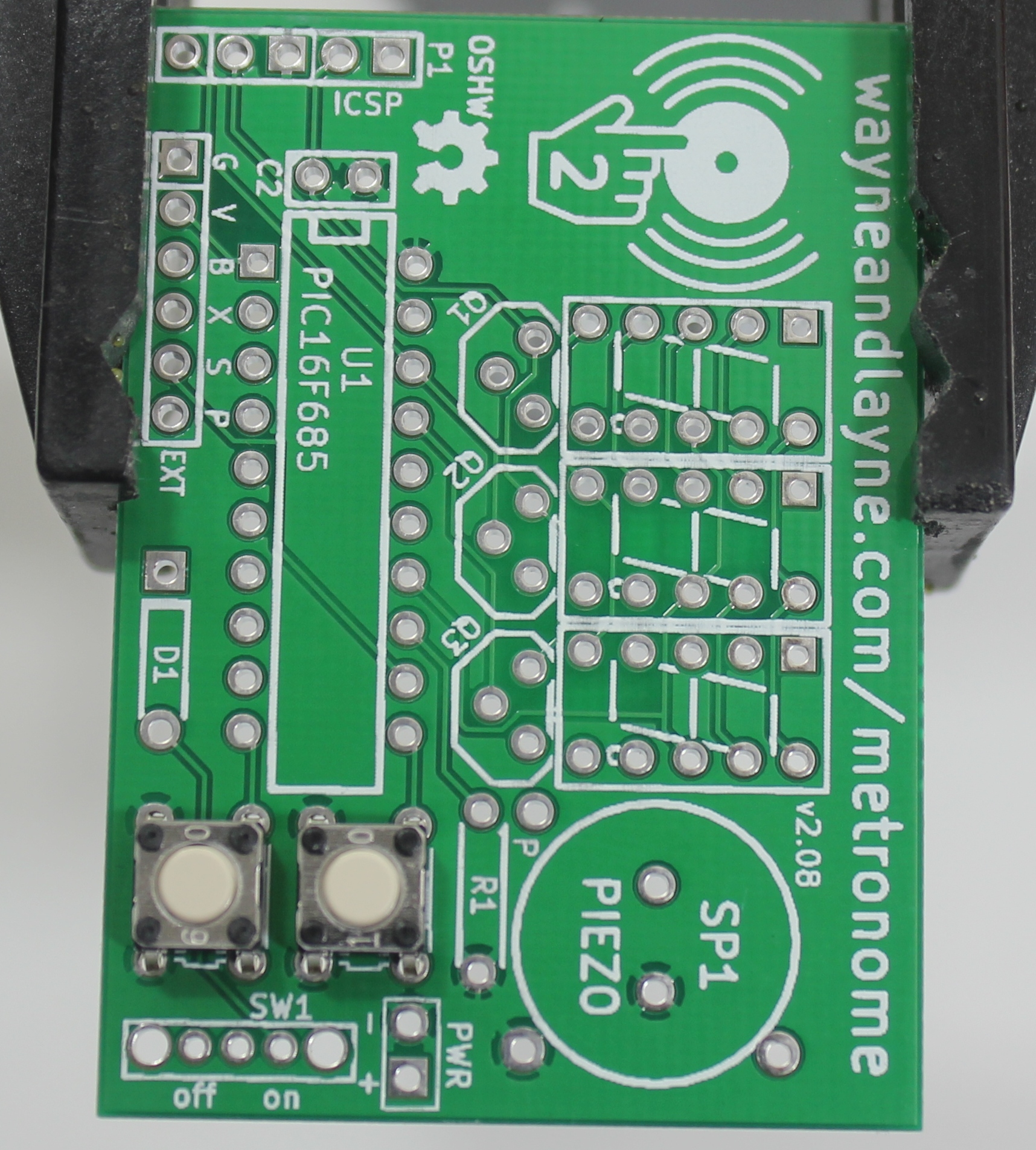
Some parts are polarized, and have to go in a certain way, but some parts are not polarized. In the steps to follow, if a part is polarized, we mention which way it must be installed. The PCB is also be marked to identify the polarization.
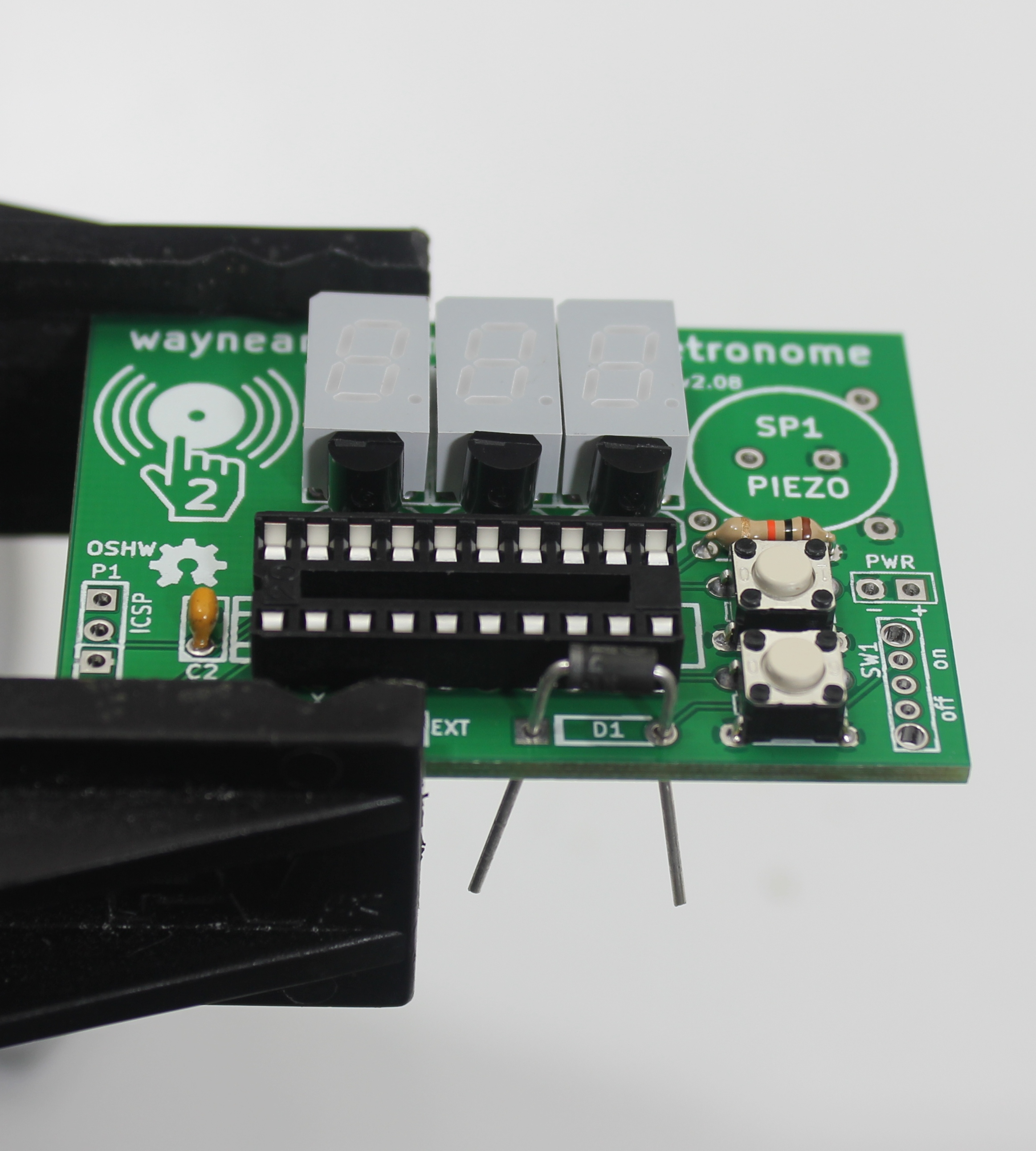
Step 2: Push Buttons
The push-buttons are used to adjust the settings of the Tap-Tempo Metronome including pattern tempo. You should be able to push the buttons right into the indicated holes in the PCB. You want the plastic base of the button to press right up against the PCB.
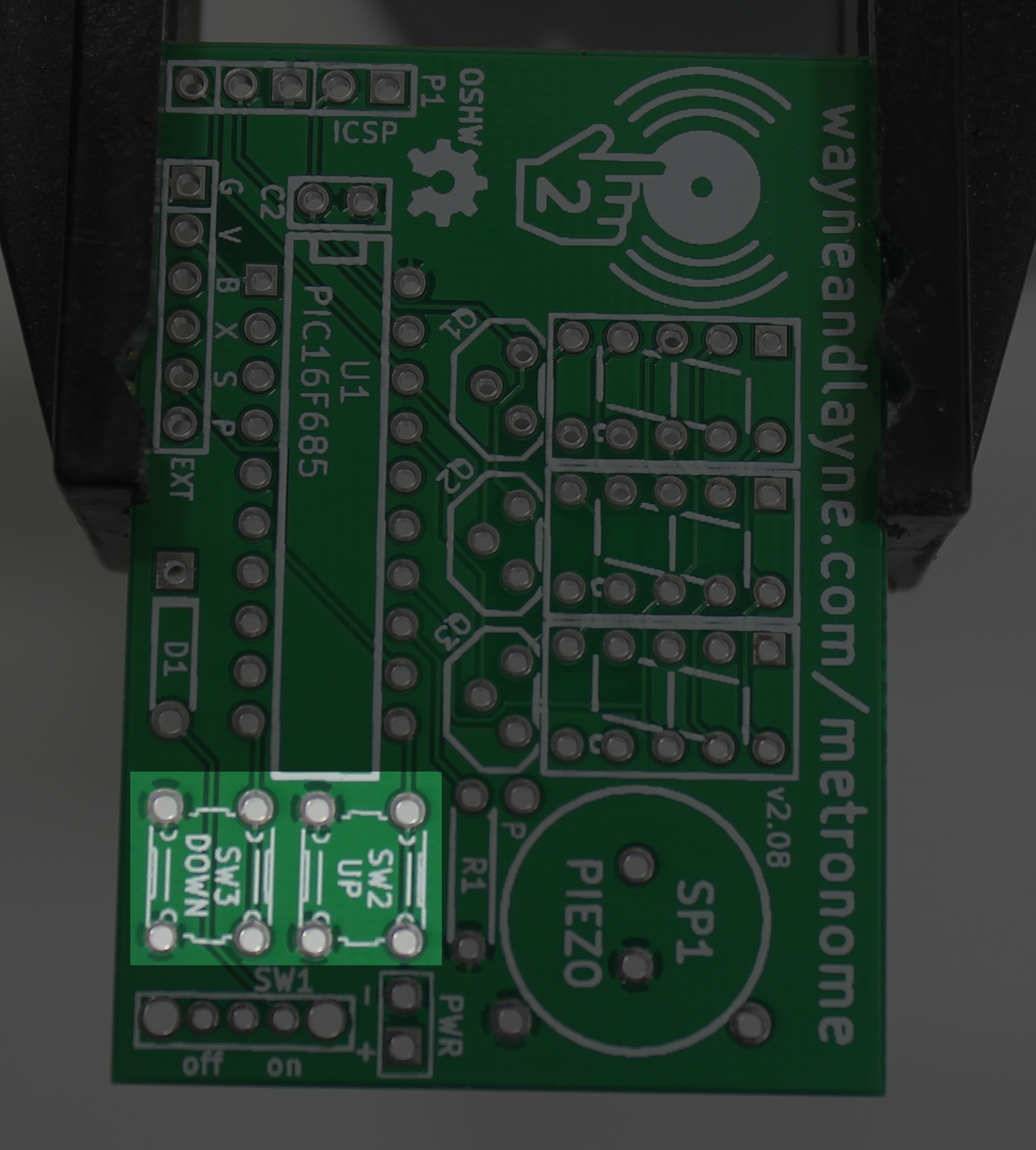
Place the two buttons on the PCB on the spots labeled SW2 and SW3. They should fit pretty snug. Turn the PCB over.
Use your soldering iron to heat up the leg of the button and the ring around the hole at the same time. Push a little bit of solder on the ring. The solder should melt and flow around the hole. If you’re having trouble, make sure the tip of your iron is tinned and shiny. Remember to heat up the pad and the pin, and you don’t need to apply a lot of solder. Don’t try to use the iron like a paintbrush. Solder all four legs of each button.
Step 3: Seven Segment Displays
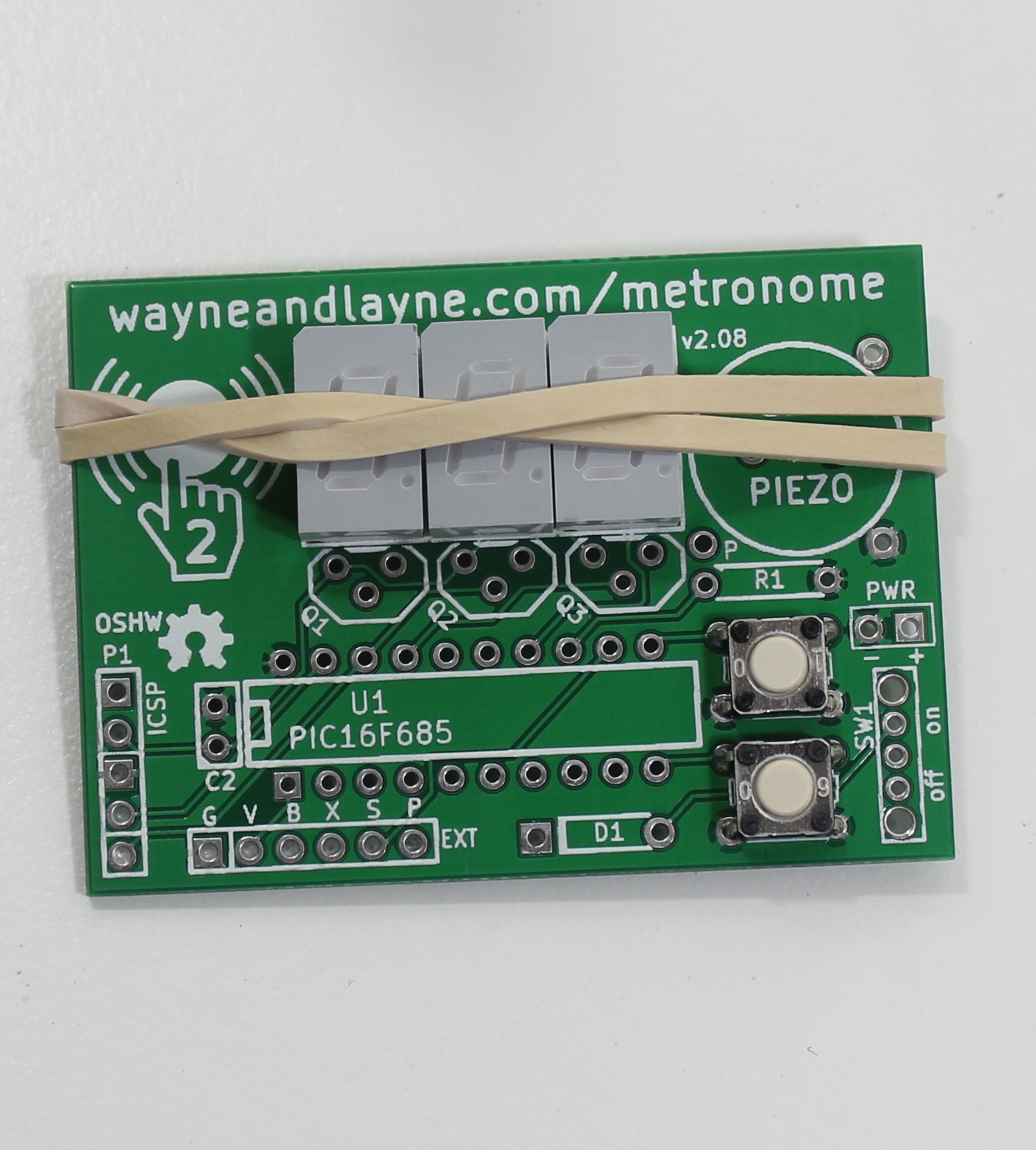
Now that you’ve gotten warmed up and practiced some soldering, it’s time to tackle the seven segment displays. Place the seven segments in the board, taking care to keep the decimal points at the bottom. It might help the alignment if you use a rubberband to secure the three seven segments against the board.
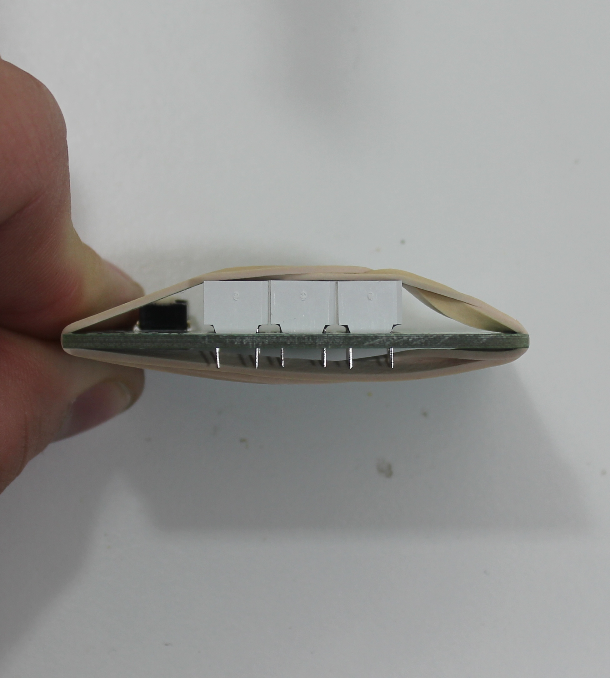
Flip the board over and put it on a flat surface like a table. Solder one leg on each display, and flip the board back over. Make sure the displays are firm against the board, and check for alignment.If the displays are crooked, you can reheat the junction and nudge the display. When you’re happy with the alignment, solder the remaining legs of the displays. The pins might look too close together, but they’re definitely solderable.
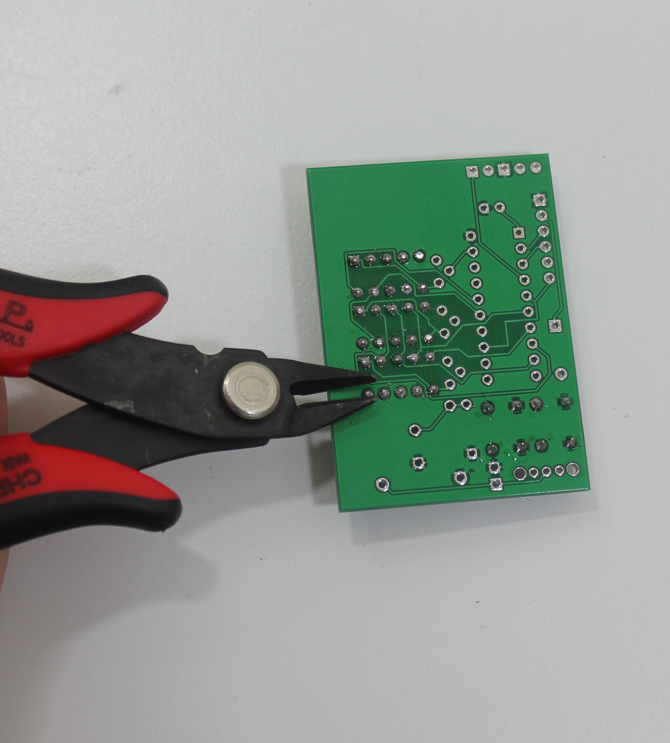
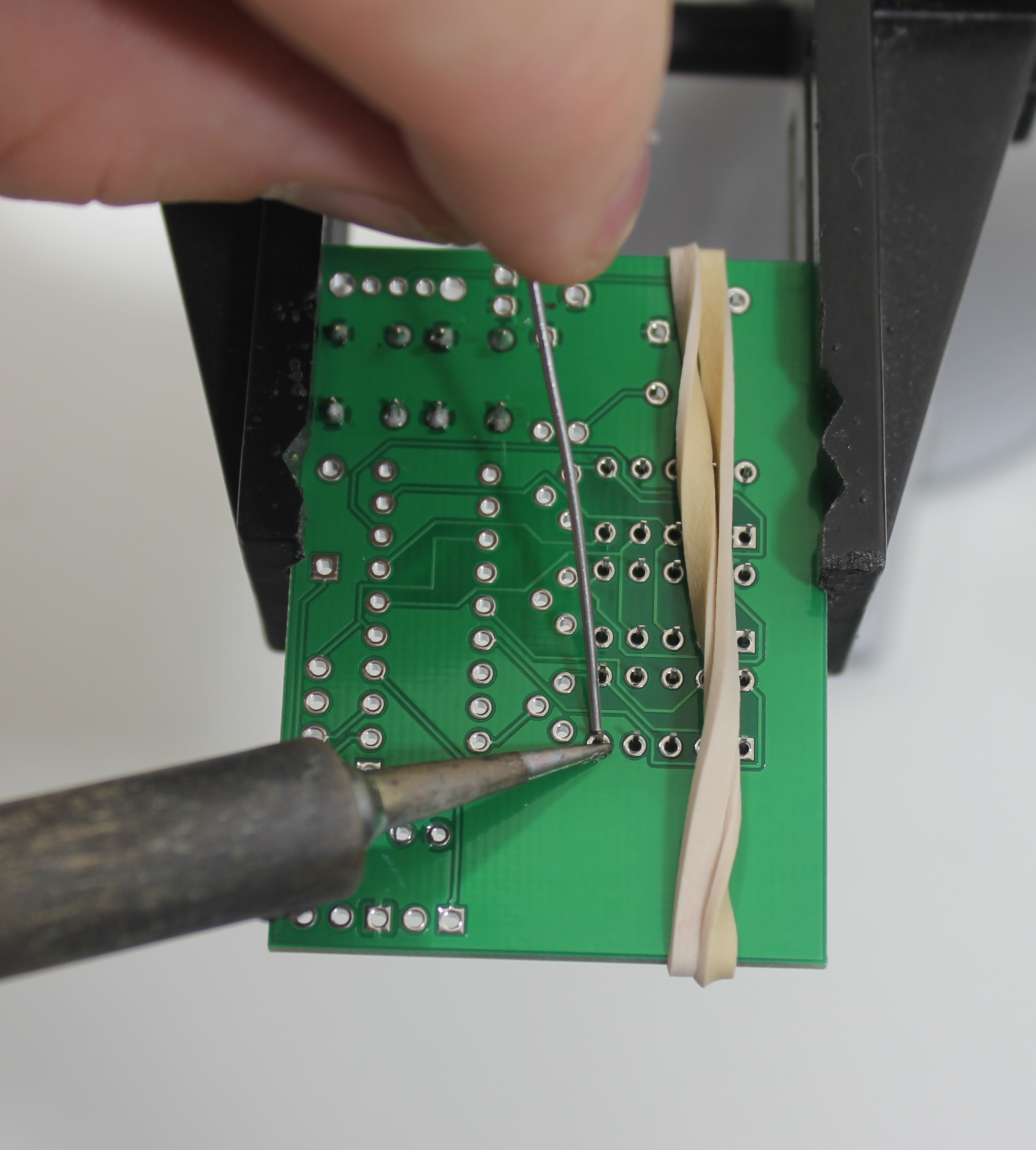
Trim the leads with your diagonal cutter pliers. Whew! It’s all downhill from here!
Step 4: Transistors
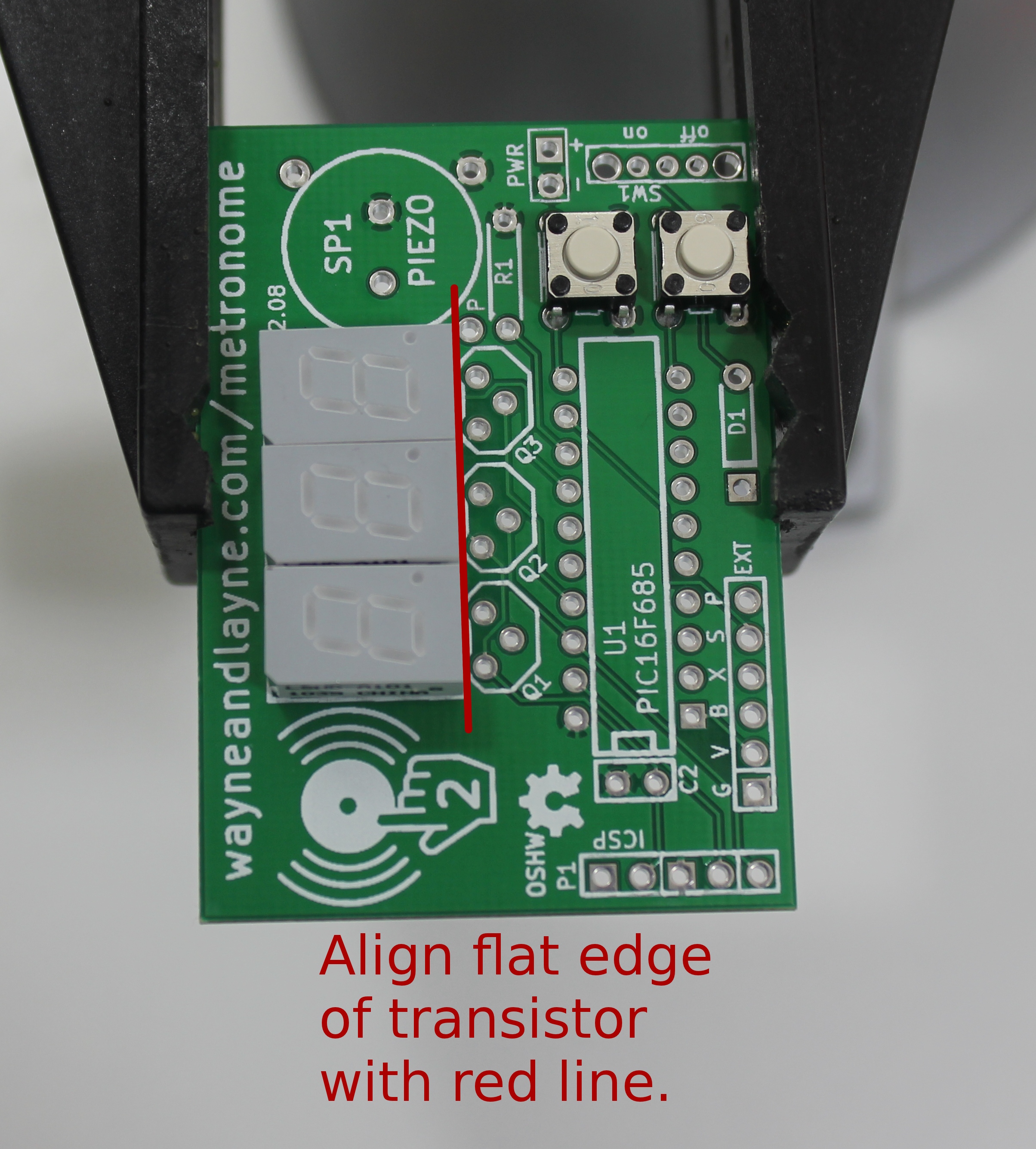
Next, insert and solder the transistors. They are labeled Q1, Q2 and Q3 on the board. The legs need to be spread a little to fit into the board. The orientation matters, so make sure to follow the white drawing on the board. Make sure the flat side of the black transistor package is facing the seven segment display, aligned with the red line in the photo below.
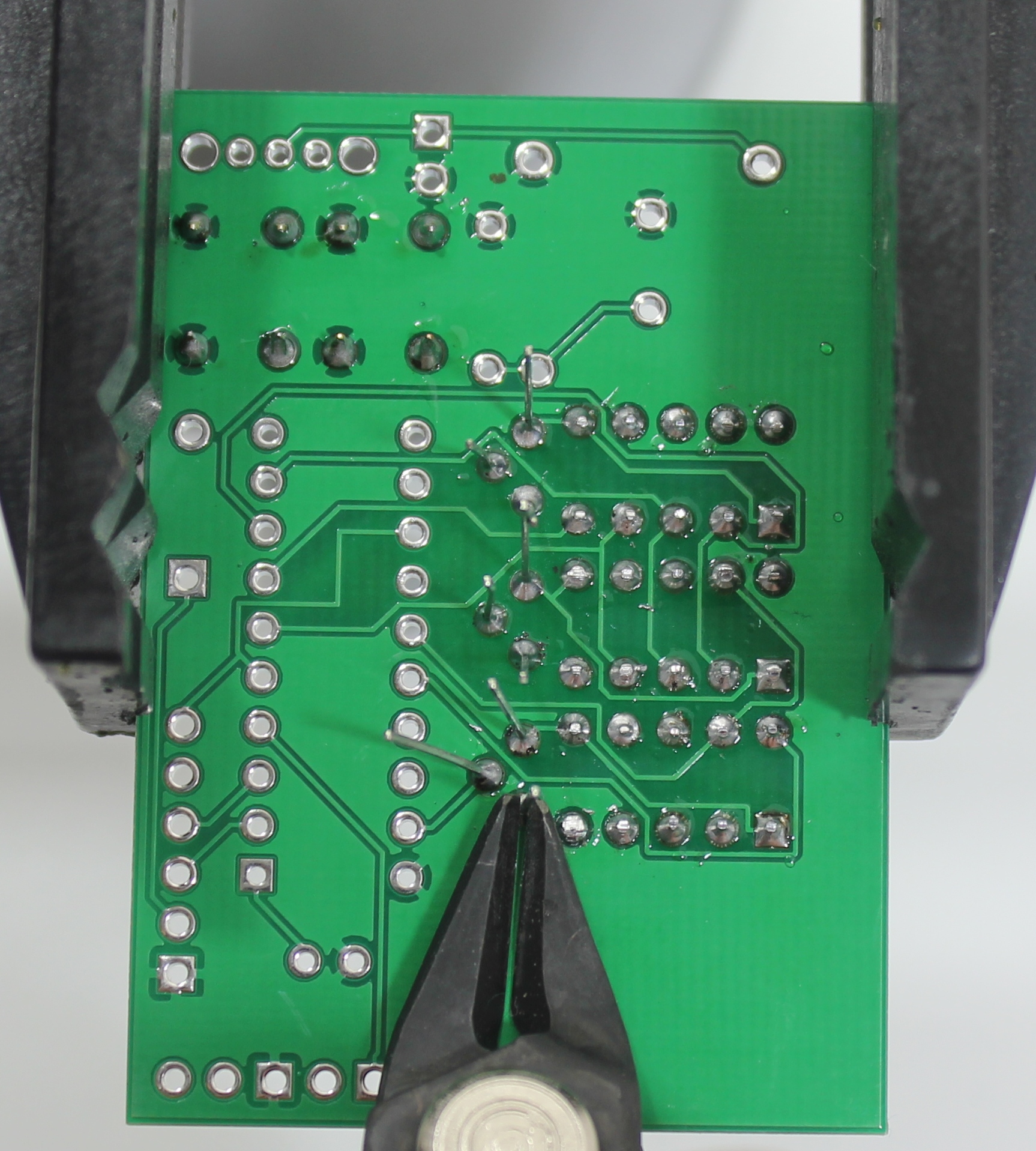
Flip the board over and solder all nine transistor leads. Trim the excess leads with your diagnonal pliers. Be sure that the leads don’t fly off and hit anybody! It might be a good idea to wear safety glasses or goggles, or at least hold your hand over the PCB to prevent the trimmed leads from flying all over the place.
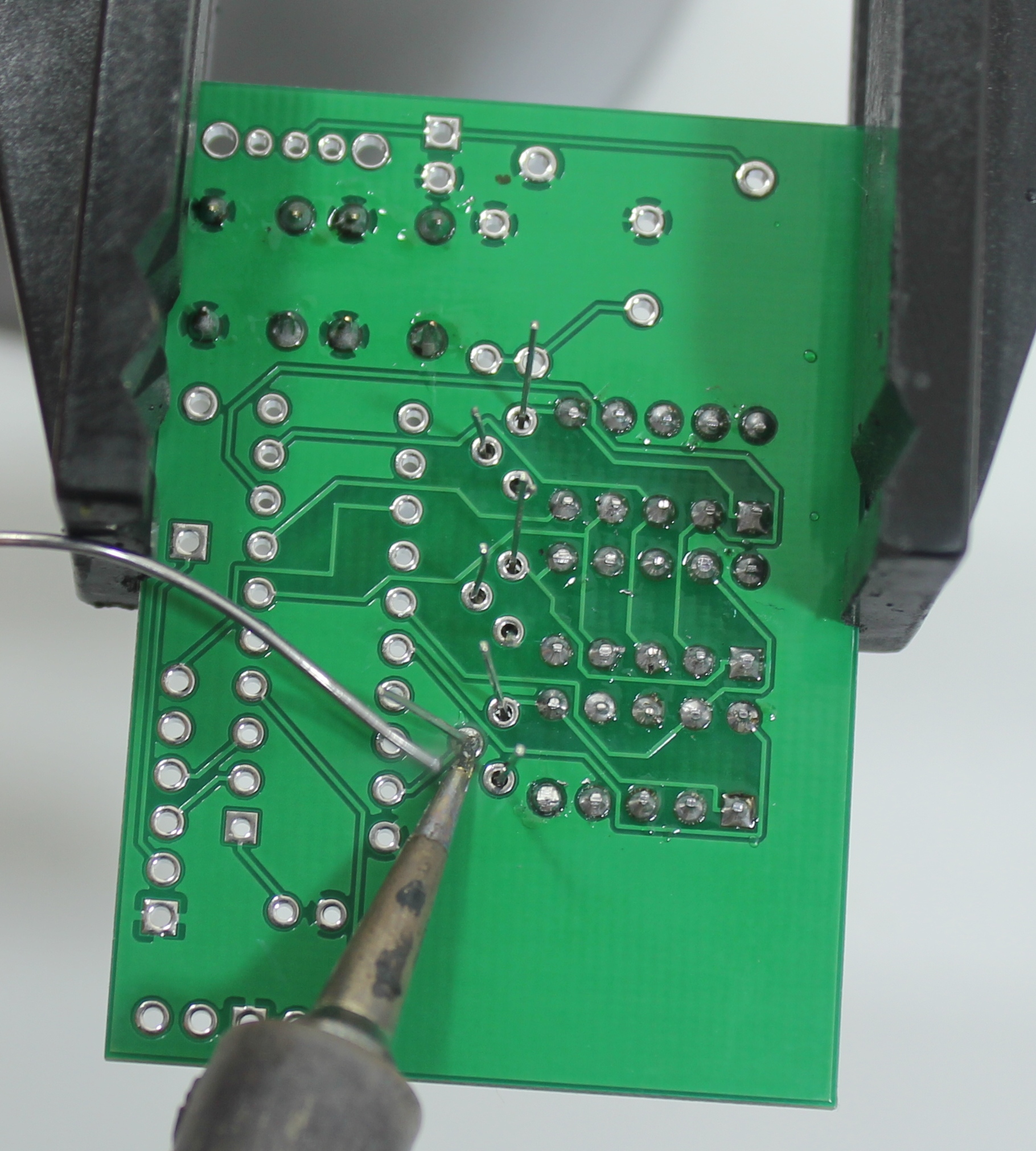
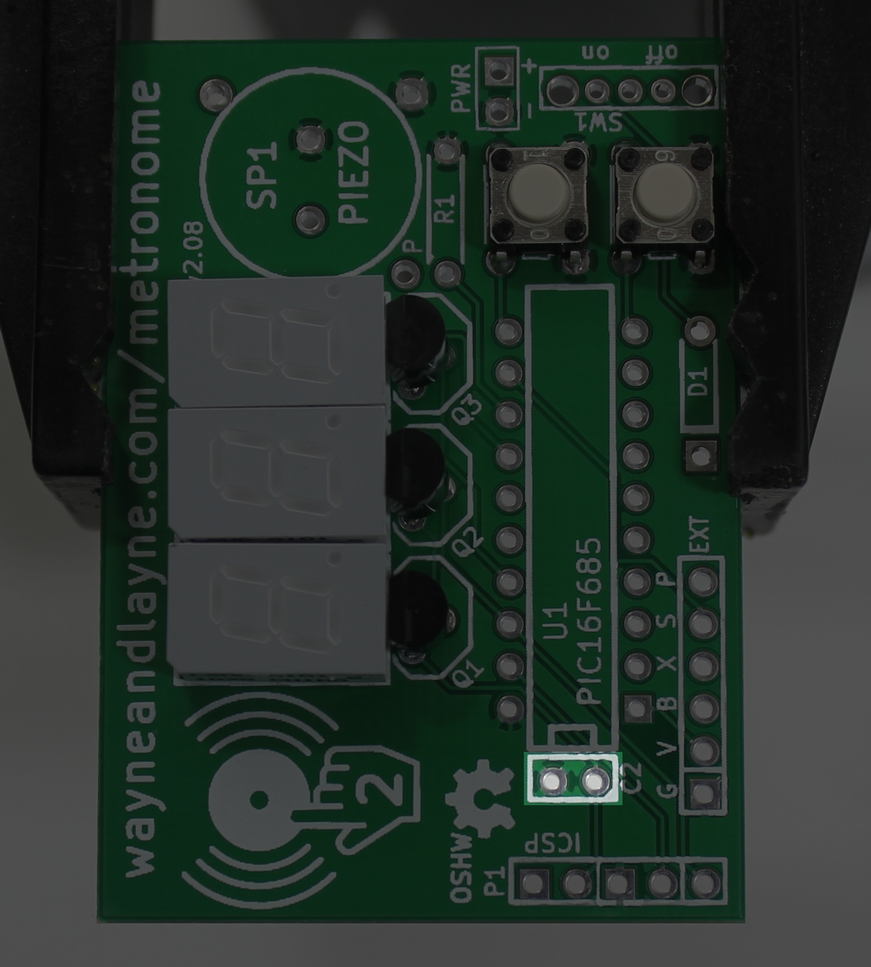
Step 5: Ceramic Capacitor
Insert and solder the ceramic capacitor, labeled C2 on the PCB. It isn’t polarized, so it can go in either way. Bend the leads a little bit so it doesn’t fall out when you flip the board over to solder the leads. As usual, trim the leads after soldering.
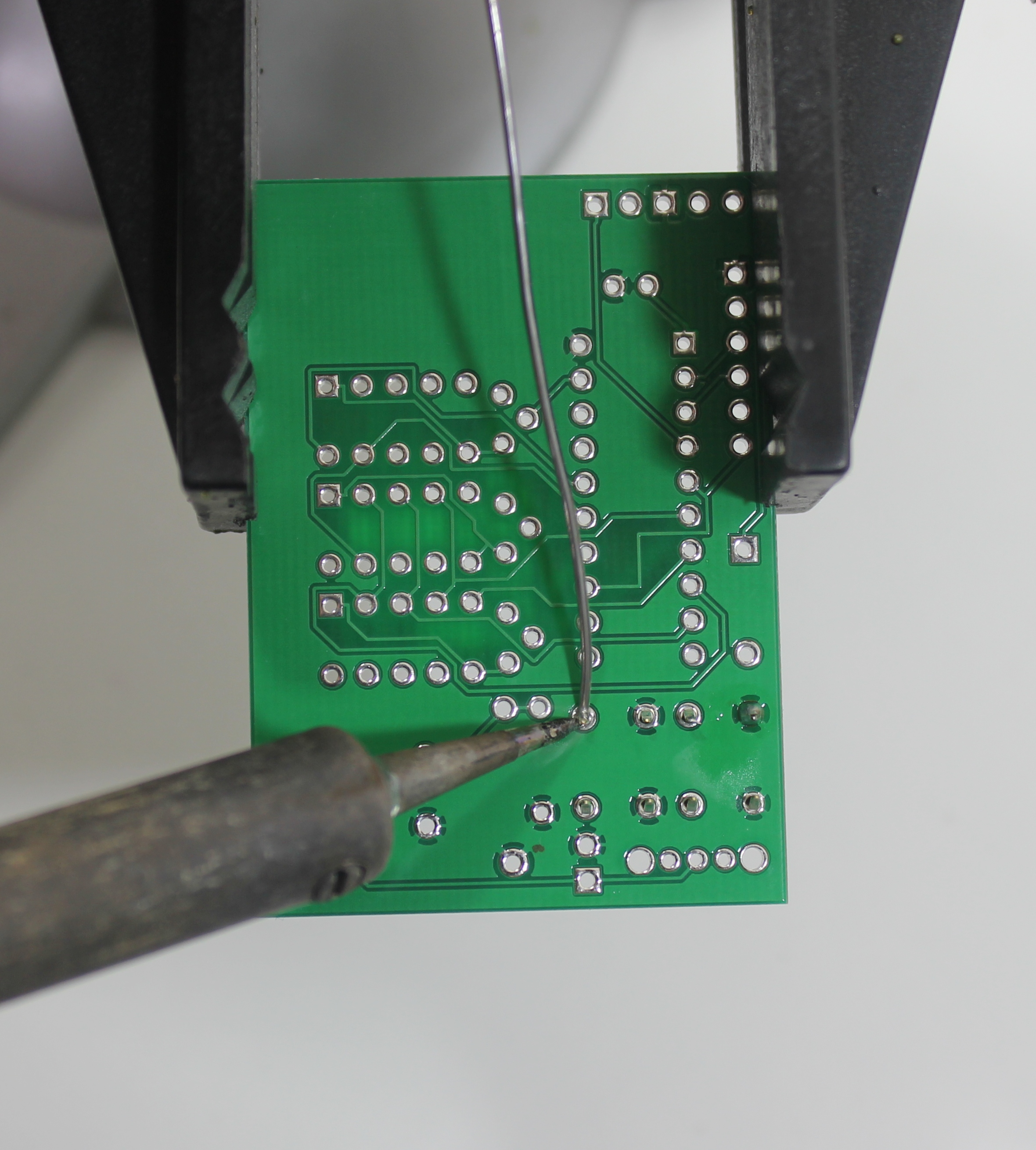
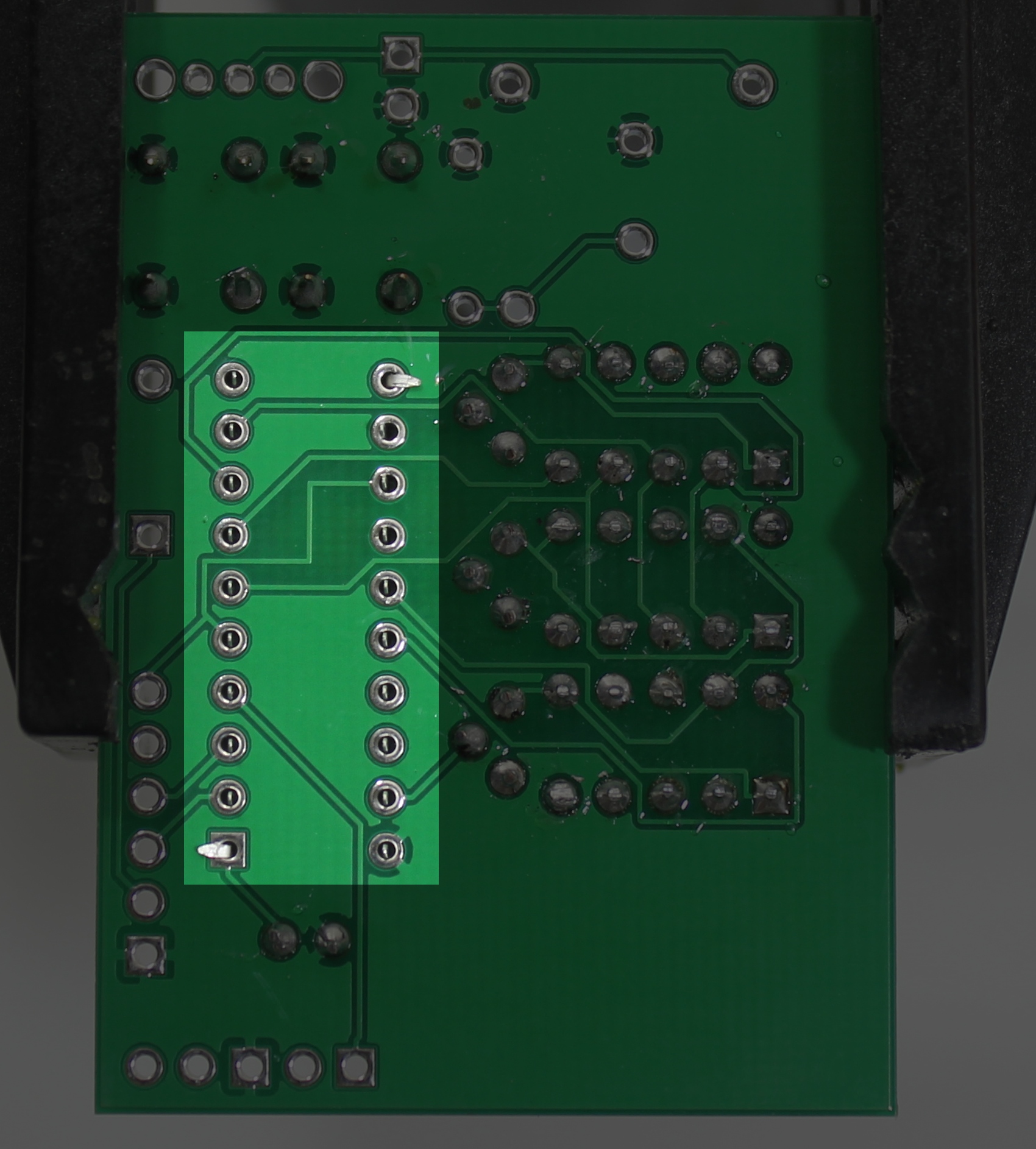
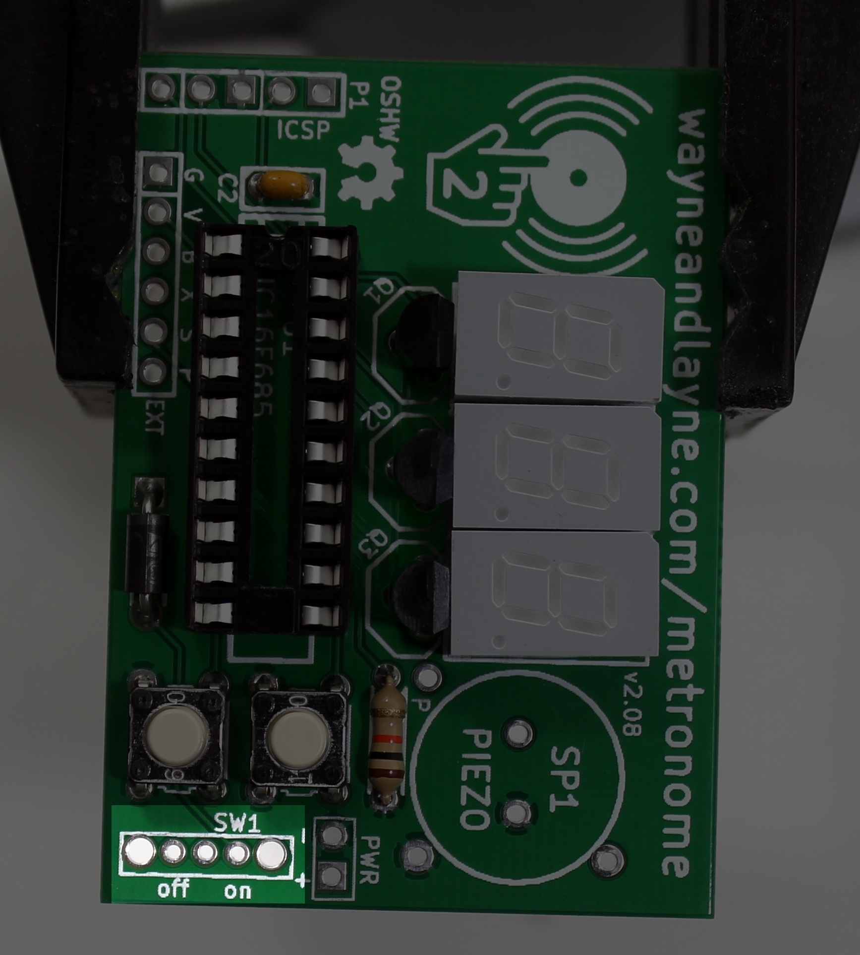
Step 6: Chip Socket
Insert the socket into the board. The footprint on the board is labeled U1. There is a notch in one end of the socket that should line up with the notch in the drawing on the PCB, next to the ceramic capacitor (C2) that was just installed. It usually helps to bend a couple of the legs to keep the socket in place while soldering. Take care to ensure that the socket is flush against the PCB while soldering, because it can be difficult to insert a chip into a crooked socket. Like the seven segment displays, you might want to solder only one pin at first, and then check the alignment. If the socket is crooked, you can melt that pin’s solder and push the socket into place. Once it is aligned, solder the rest of the socket’s pins.
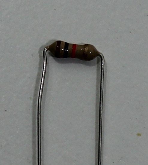
Step 7: Resistor and Power Protection Diode
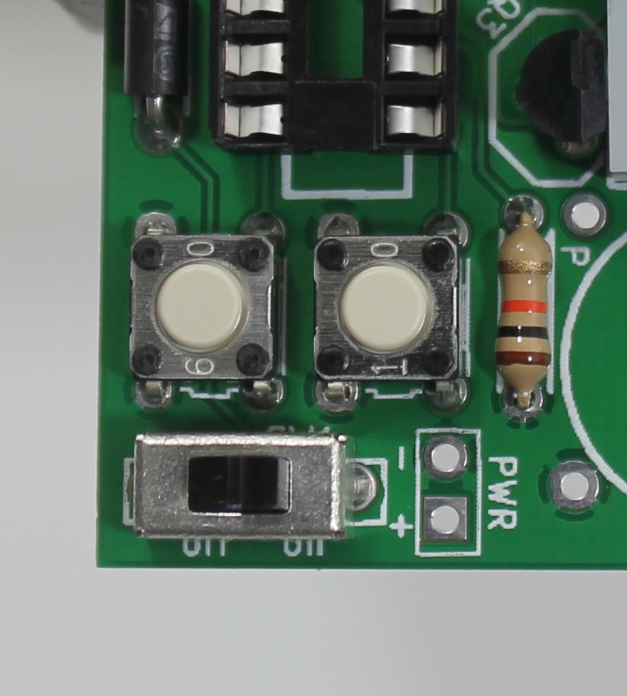
Bend the resistor as shown and place it on the board. It belongs just above the push buttons, and is labeled R1. This part isn’t polarized so it can be installed either way. Insert it through the holes in the PCB and bend the leads outwards slightly to hold it in place. Solder it down and trim the legs.
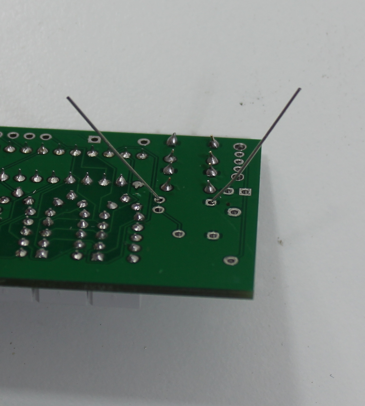
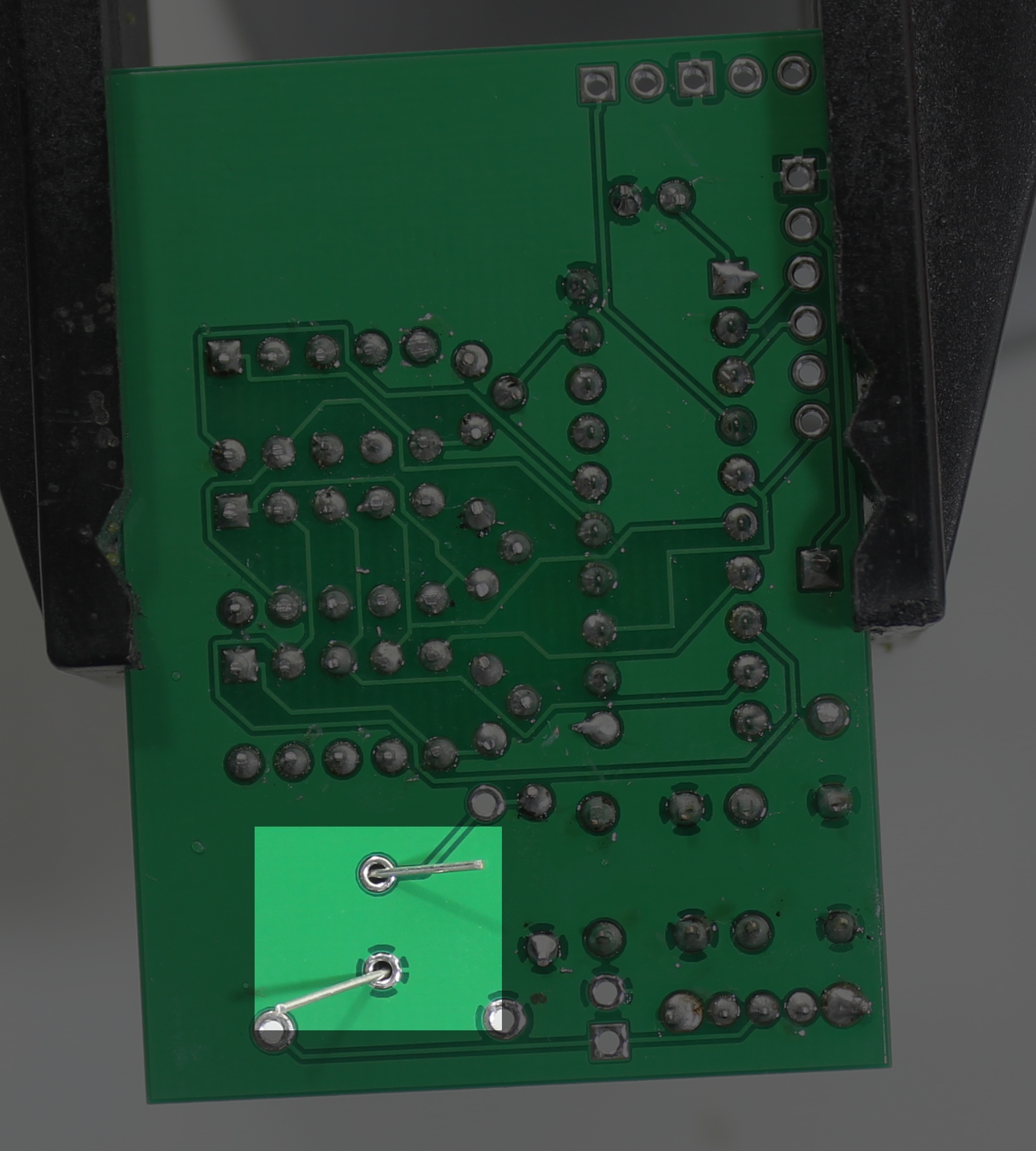
Bend the much thicker leads of the power protection diode in the same was as you did the resistor. This diode is labeled D1 and is at the bottom of the board underneath the chip socket. Unlike the resistor, this diode is polarized and can only be inserted a certain way. Align the thick silver stripe on the diode with the thick white line on the PCB, on the left side of the diode footprint, the square pad. It should look like the image below. Push the diode flat agains the PCB and bend the leads out slightly. Solder and trim the leads. When you’re finished with this step, the resistor and diode should both be flat against the PCB.
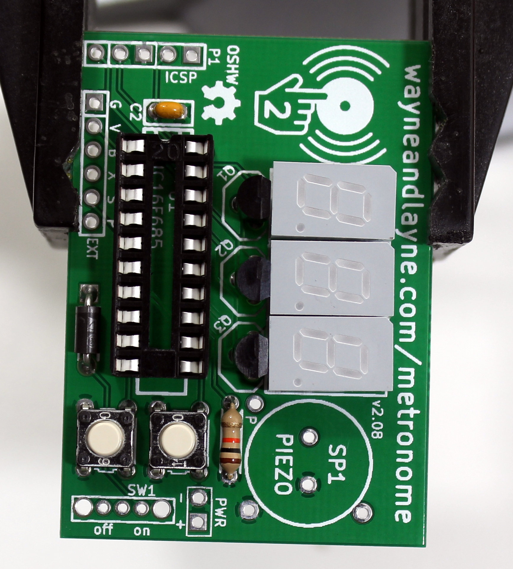
Step 8: Power Switch
Insert the power switch on the bottom corner next to the pushbuttons. The power switch is not polarized and can be installed either way. Solder down all five pads. You shouldn’t have to trim the leads. You might have to solder one pad first, then hold the switch flush against the PCB while re-melting that soldered pad. Be careful not to burn yourself with the hot switch case!
Step 9: Piezo Buzzer
Place the piezo (SP1) into the board. You’ll notice it has two little pegs underneath that keep the case off the board. Use your finger to keep those pegs pressed firmly and squarely on the board. You can bend the leads to keep it in place, but you should still hold your finger on the top of the piezo while soldering it (or re-melting a soldered lead). Solder it, and clip the legs flush against the solder ball.
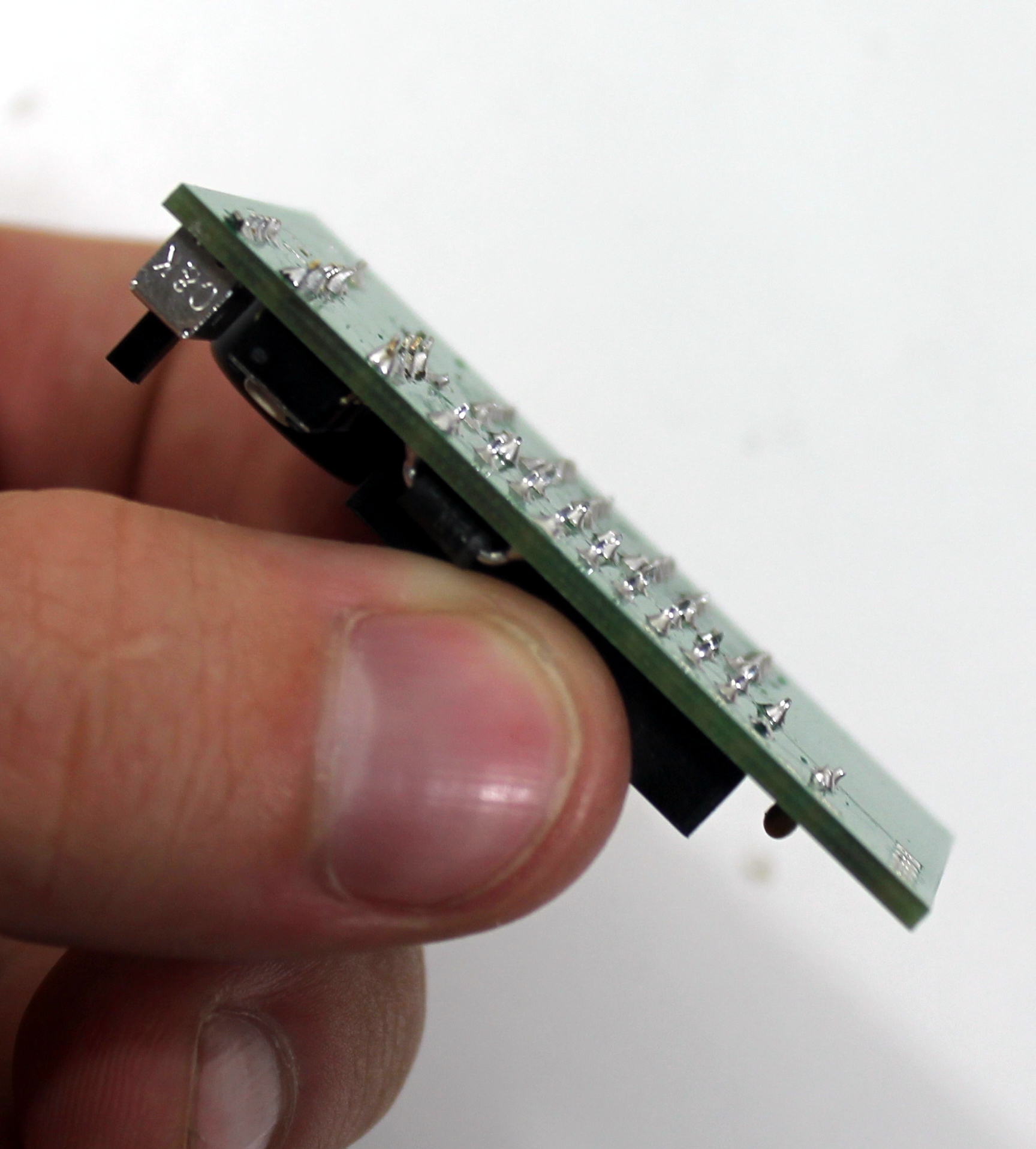
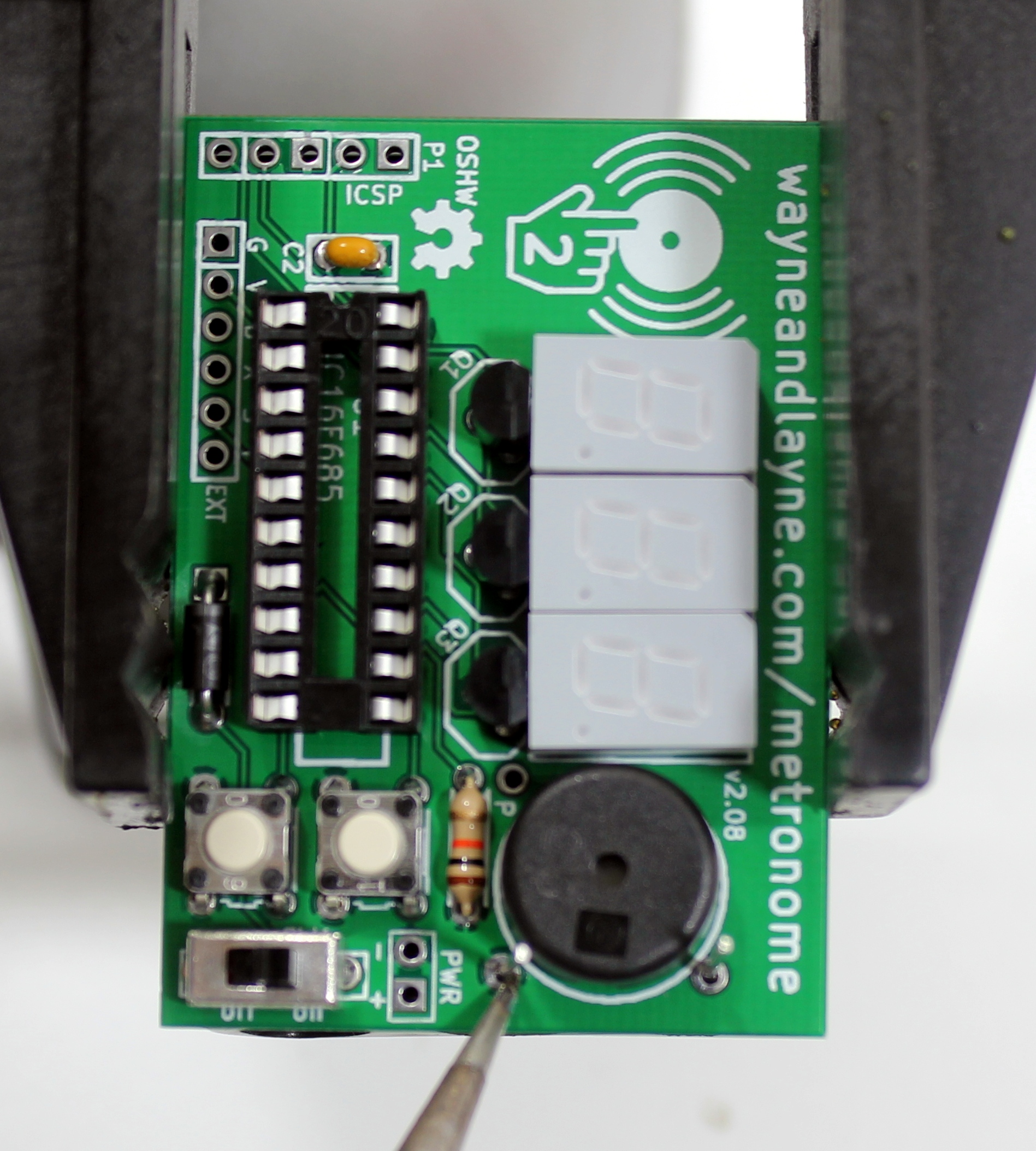
Step 10: Review
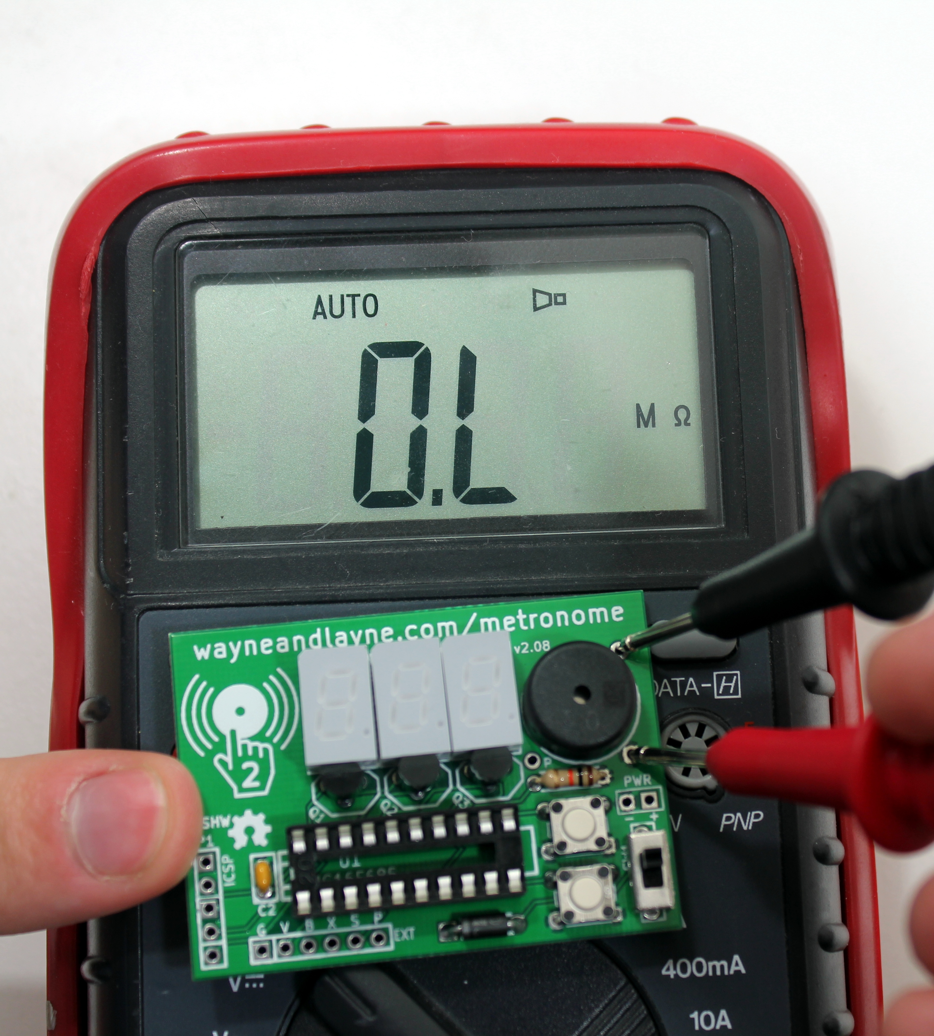
At this point, you should review your work. Are there any parts left over? Inspect your solder joints. Is there solder connecting any neighboring pads? There shouldn’t be! Are any component leads hanging too long? If there is any wire past the solder joint, trim it off with the diagonal pliers. If you have a multimeter (you should!), you can measure the resistance between the two pads for the battery holder. It should say there’s no connection, or have an extremely high resistance. If it says there’s a low resistance or a short, review your soldering again and look for the short. In the picture below, the multimeter is measuring resistance, and the value “0.L” means that the measured resistance is out of range, and is too large to measure. This means there is an open circuit (very large resistance) between the two battery pins, just what we want.
Step 11: Insert Processor Chip
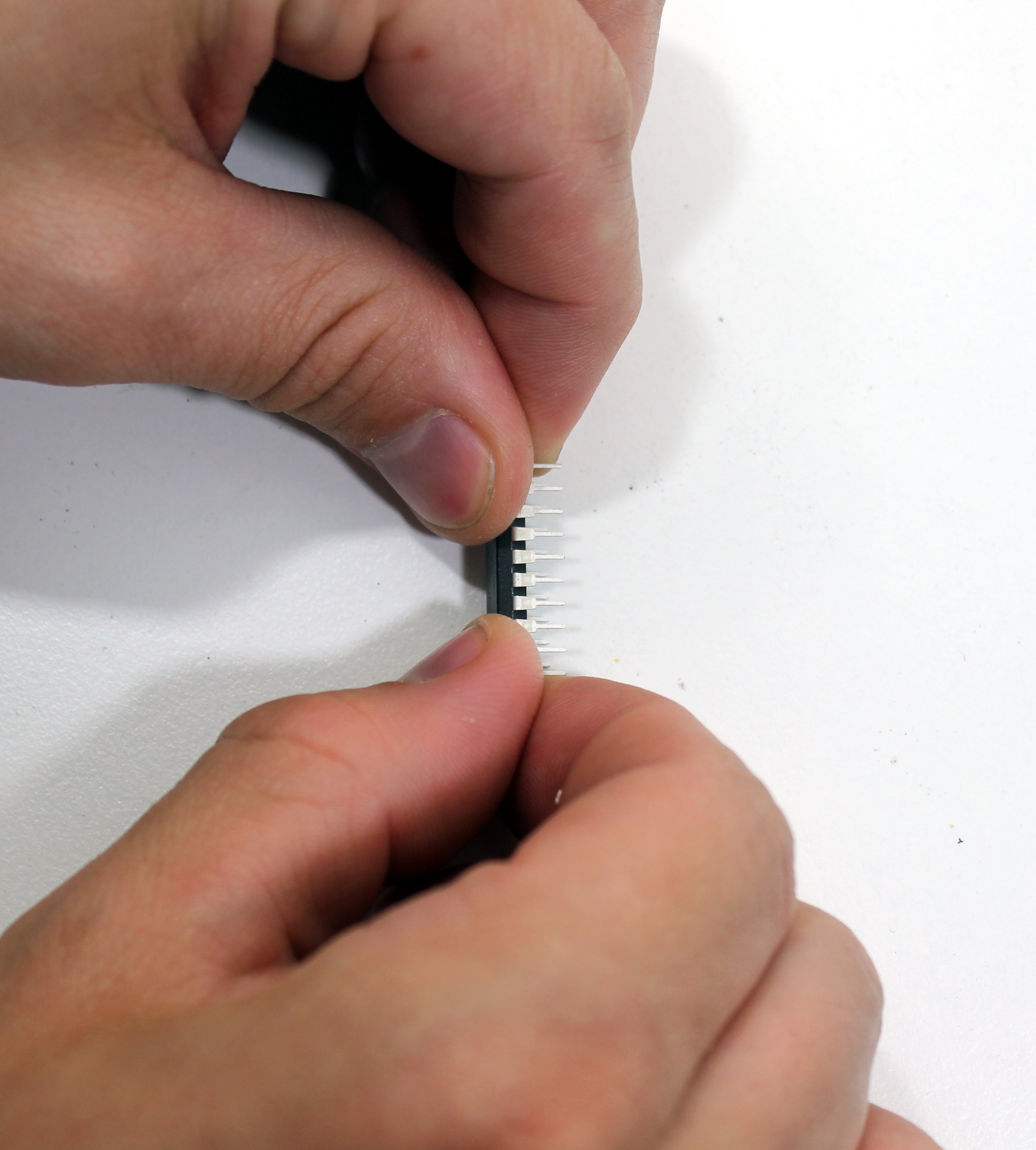
Chips in DIP form usually have legs that are bent out too far to fit easily into sockets. One way to slightly (but uniformly!) bend the legs in is to press the chip against a table as shown in the photo. Insert the chip into the socket, taking care to get all the pins aligned in their holes. Make sure to put the chip in the right way! The notch in the chip lines up with the notch on the board, and the notch in the chip socket (if you aligned the socket properly!).
Step 12: One Last Test
The most common issue that can affect your Tap-Temp Metronome is bad solder connections. After you solder on the battery holder to the back of the PCB it becomes really difficult to troubleshoot and touch-up all the solder joints on the back of the PCB, so we should test the Metronome before attaching the battery holder. Put the batteries into the battery holder and stick the leads through the holes. Twist the battery holder slightly so the two leads make good, solid contact with the holes. Flip the power switch to ON and you should hear a beep and see “r22” (or some other number) on the seven-segment displays. This confirms that the piezo output and the displays are working correctly. Try tapping the piezo with a pen or pencil a few times. The digits should flash brighter when each tap is detected. After tapping a couple of times, wait two seconds and the metronome should start beeping at the same tempo you used for the input taps. This confirms that the tap detection is working correctly. While the Metronome is playing back your tempo, use the up and down push buttons to adjust the temp. This confirms that the buttons are working correctly. If everything works correctly, continue on to the next step and solder down the battery holders. If things aren’t working try re-melting the solder on the relevant connections. If any of your solder joints are not shiny and clean and smooth, try re-melting them and add just a tiny amount of extra solder to clean it up.
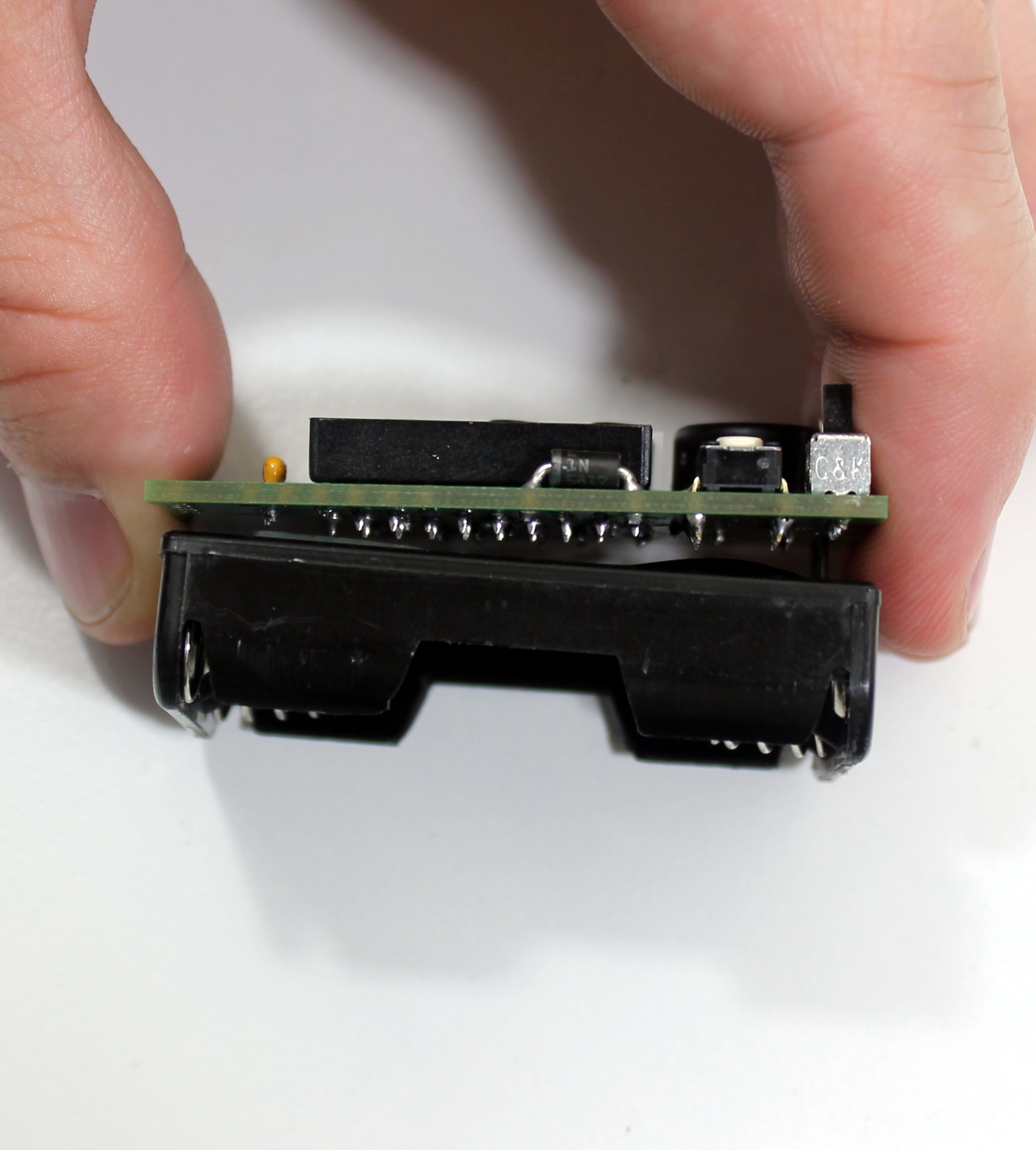
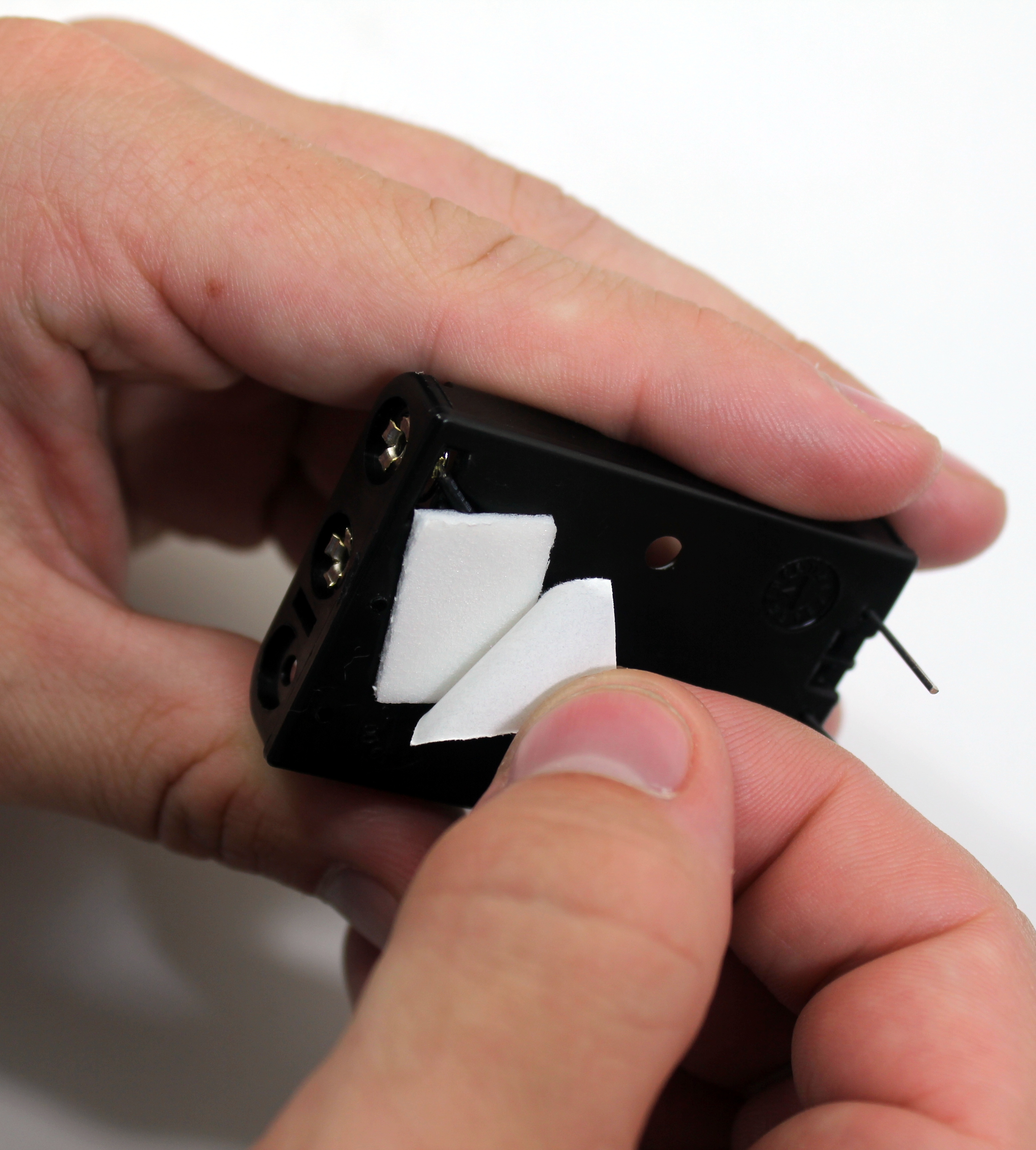
Step 13: Battery Holder
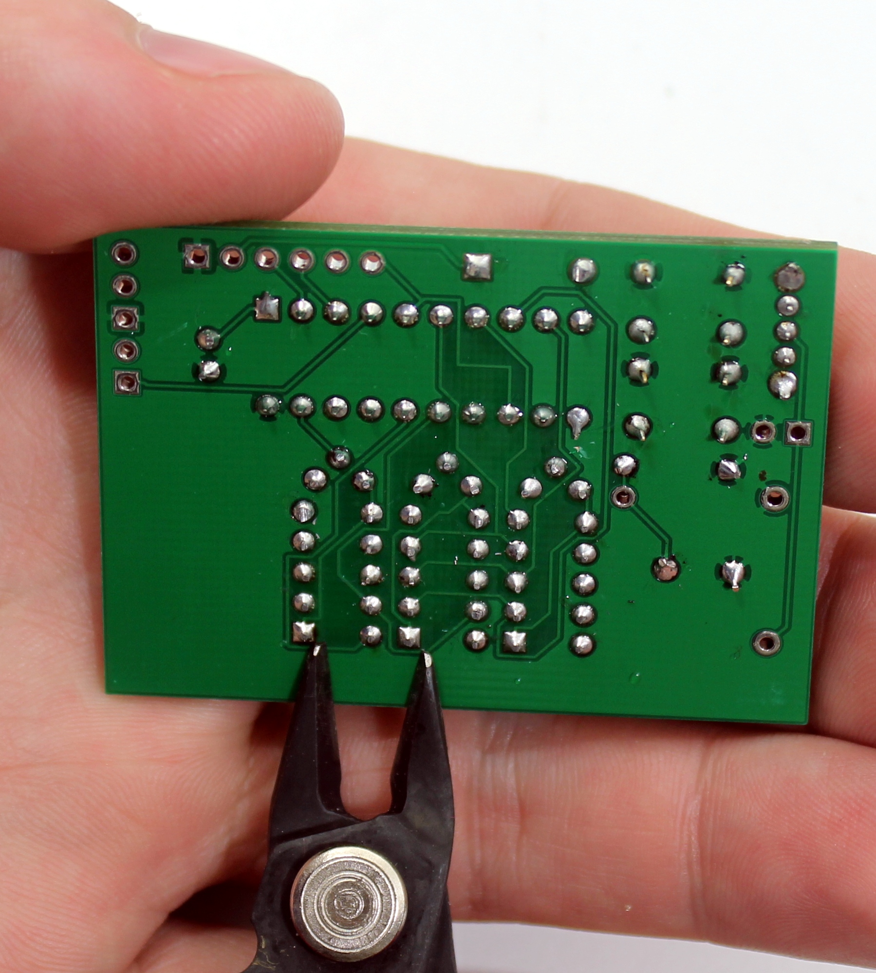
The battery holder is going to attach to the board with sticky foam tape, and also be soldered. In the previous step you should have trimmed off any component leads that were too long, so take a look at your board’s underside to make sure all the leads are trimmed down. Your battery holder may or may not already have the foam tape attached. If the piece of foam tape is not already attached, remove one side of the paper backing and firmly press the sticky side to the back (flat side) of the battery holder.
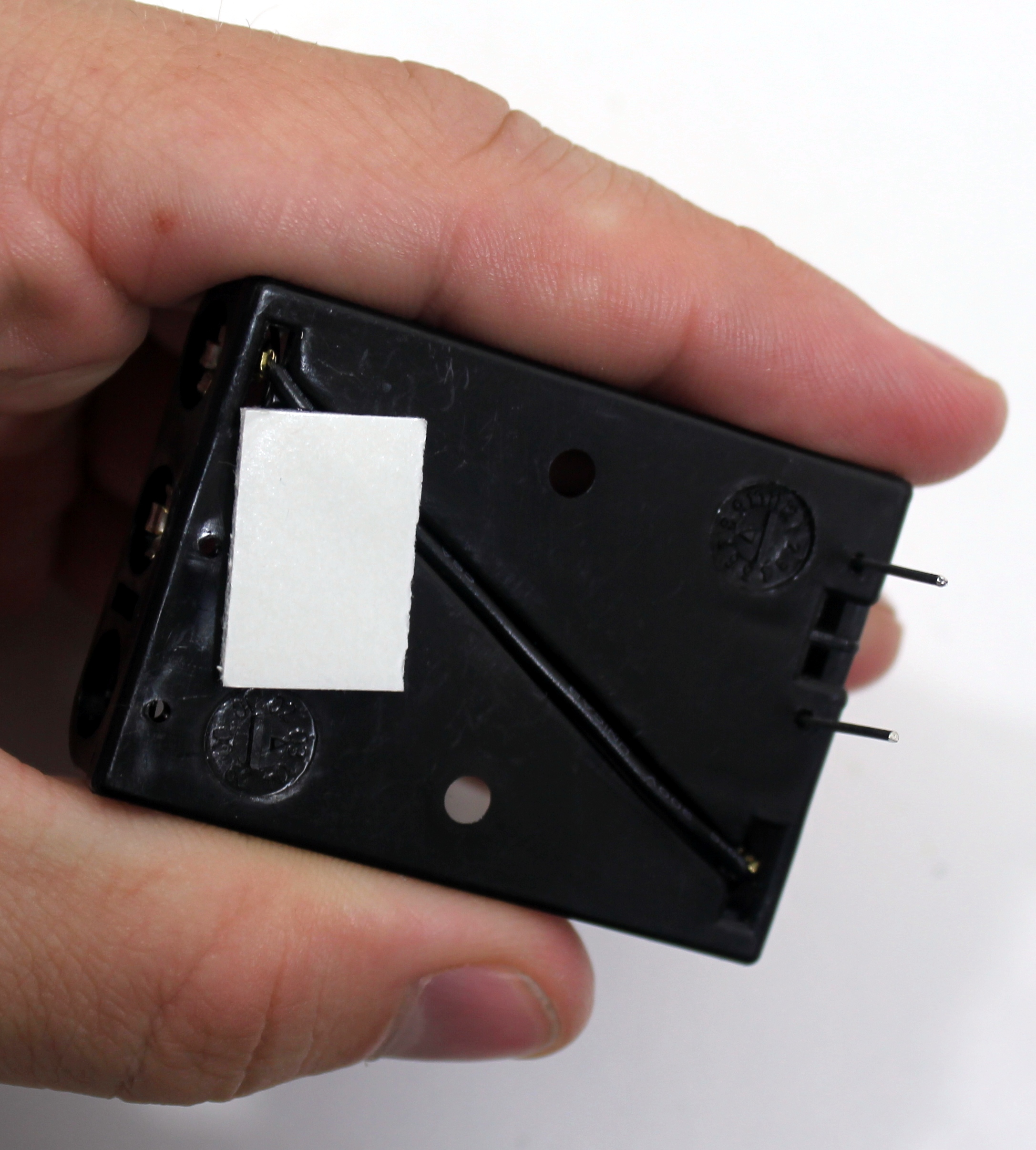
Remove the paper backing from the foam tape on the battery holder, and insert the leads of the battery holder through the back of the holes in the PCB and slowly press the battery holder against the PCB. Be firm, but be careful not to warp the battery holder by pressing unevenly. Solder the leads. These may take a little longer to solder–the thick leads can require a lot of heat. Clip the leads.
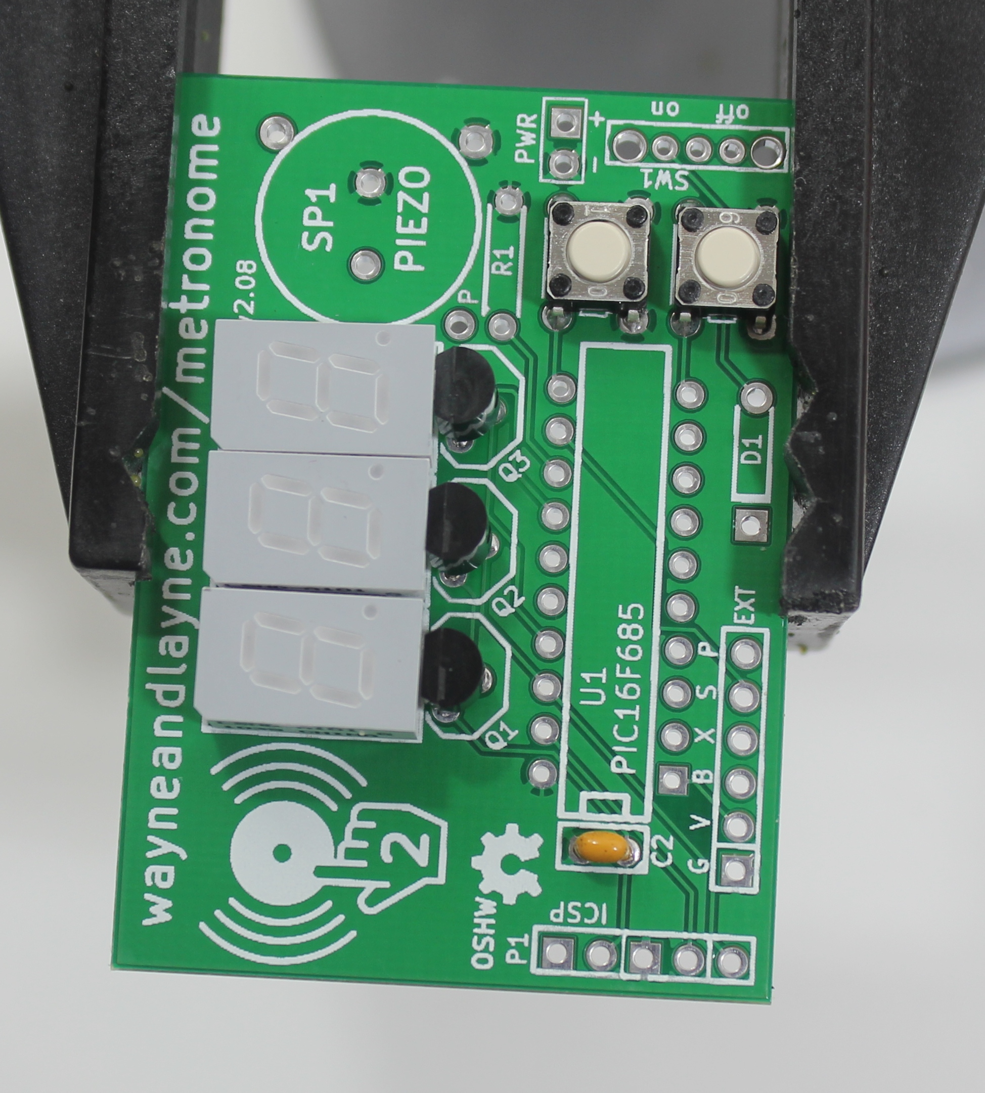
Step 14: Completion!
Give the completed board a final look over, checking for loose solder connections or shorted pads. Congratulations! You’re now the proud owner of a Tap-Tempo Metronome. Install some AAA batteries and give it a try!
H