


Bricktronics Megashield Parts List
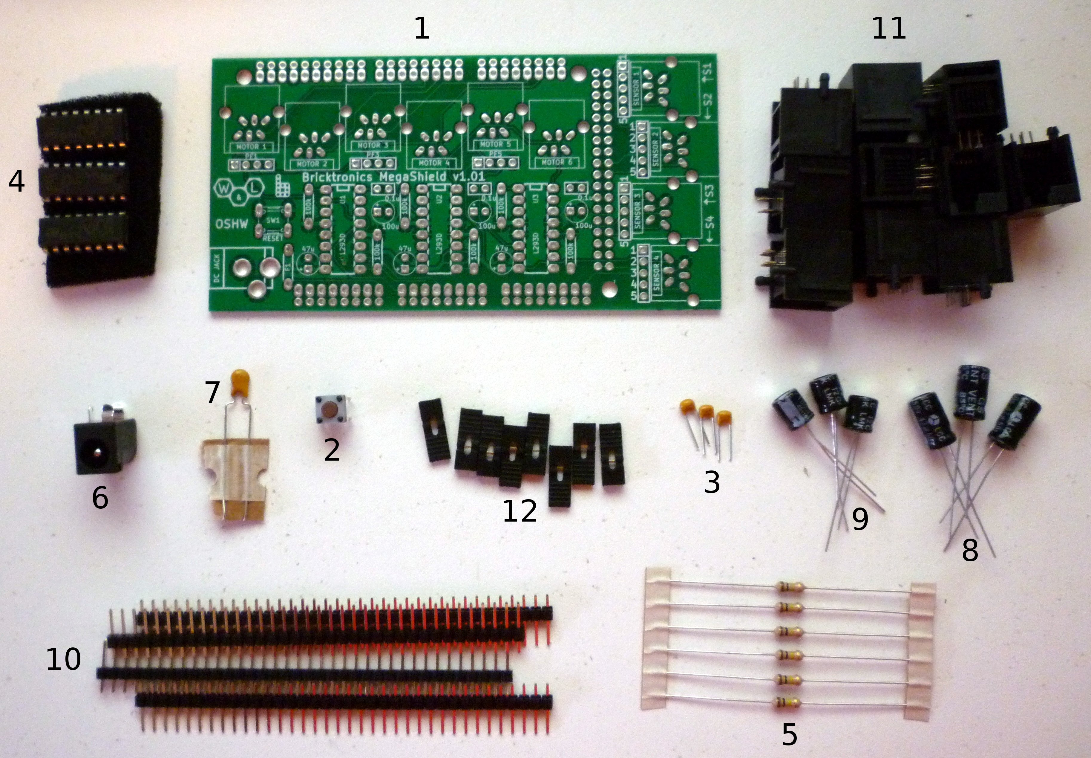
This is a list of all the parts used in the Bricktronics Shield, along with a little bit of explanation about what each part does in the circuit.
- (1) Bricktronics Megashield Printed Circuit Board – PCB
- (1) Push Button – SW1
- (3) 0.1uF Ceramic Capacitors (3) – Labeled “0.1u”
- (3) L293D Motor Driver Chips – U1, U2, U3
- (6) 100 kΩ resistors – Labeled “100k”
- (1) DC power jack
- (1) PTC fuse – F1
- (3) 47uF Electrolytic Capacitors – Labeled “47u”
- (3) 100uF Electrolytic Capacitors – Labeled “100u”
- (4 strips) Breakaway male headers
- (10) NXT-compatible Sockets
- (8) Shorting Jumpers
What does each part do?
There’s more information about the design of the Bricktronics Megashield at the Design page.
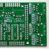
Bricktronics Megashield PCB (Back to list)
The Bricktronics Shield PCB is a professionally made printed circuit board with soldermask for easy soldering and silkscreen printing for easy assembly.
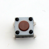
The push button acts the same as the reset button on the Arduino board. The specific pushbutton we use is the B3F-1000 by Omron Electronics.
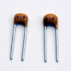
0.1 uF Ceramic Capacitors (Back to list)
The 0.1 uF ceramic capacitors are used to help smooth-out spikes and ripples in the power supply voltage caused by sudden current draws from motors or sensors.
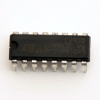
L293D Motor Driver Chips (Back to list)
The L293D is a very popular and common motor driving chip, consisting of four half-H-bridges (effectively two full H-bridges). An H-bridge circuit consists of four transistor switches that allows electricity to flow in either direction through a load, such as the motors we are driving on the Bricktronics Megashield. Each chip can drive two motors, so we need three L293D chips to drive the six motors supported by the Megashield.
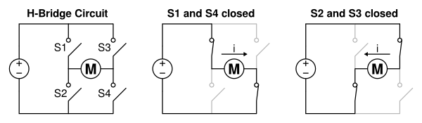
As shown in the image above, if switches S1 and S4 are closed, the current flows through the motor from left to right. If switches S2 and S3 are instead closed, the current flows the opposite direction through the motor. By controlling which switches are open and which are closed, the Arduino can drive the motor to rotate in either direction. It is very important to never have switches S1 and S2 or S3 and S4 closed at the same time, since that would cause a short-circuit between the motor voltage and ground! Since the Arduino cannot provide much current per pin (only enough to light an LED!) the L293D provides the big transistors that are needed to switch the higher current demanded by the motor (up to 600mA, about 20 LEDs-worth!). By switching the control signals on and off very rapidly, the Arduino can drive the motor at different rotation speeds.
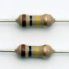
100 kΩ Resistors (Back to list)
Resistors are a basic circuit component that resist the flow of electricity by generating a voltage in proportion to the current flowing through it and the resistance value of the resistor it self. It is a simple linear relationship expressed with Ohm’s Law: voltage = current * resistance. The 100k resistors are used in a “pull-down” role, where they make the L293D’s motor enable pins have a “default value” of 0 volts (Logic Low). This makes it so that the motors should be disabled when the Arduino is not actively driving the enable signal to 5 volts (Logic High). This prevents the motors from spinning out of control when the Arduino is being reprogrammed.
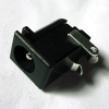
The DC jack is used to provide power to the motors, and is the standard 2.1mm center-positive type, just like on the Arduino boards. The reason we included our own DC power jack, and didn’t just use the one on the Arduino, is that the six motors require a lot of current, more than can be safely provided by the single Vin pin that connects the Arduino Mega to the Megashield. We still use that Vin pin to provide power to the Arduino, but it is only a small amount going to the Arduino. It is very important that you plug the DC plug into the jack on the Megashield, and not the Arduino, if you are using more than two motors.
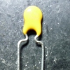
The small yellow fuse is also called a PTC (for Positive Temperature Coefficient, meaning the resistance increases as the temperature increases) and is used to supply the DC input voltage to the Arduino, so it can be powered too. The reason we added this fuse is to protect the single Vin pin (connecting the Arduino Mega and the Megashield) from too much current. Normally, you connect the DC power supply to the DC jack on the Megashield, which powers the motors directly without sending all that current between Arduino and shield. If you accidentally connected the DC power supply to the Arduino instead of the Megashield while running many motors, a large amount of current will be drawn from the Arduino through the single Vin pin, which could cause it to get really hot or even melt! The PTC helps protect the pin by limiting the maximum amount of current that can be transferred through the Vin pin. If too much current is drawn, the PTC fuse will “trip”, and experience a drastic increase in resistance, which will limit the amount of current that can be drawn.
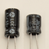
47uF and 100 uF Electrolytic Capacitors (Back to list)
The 47 uF and 100 uF electrolytic capacitors are used to help smooth-out spikes and ripples in the power supply voltage caused by sudden current draws from motors or sensors. These capacitors are much larger than the smaller ceramic capacitors also included, and are better at helping supply larger currents to help reduce power supply voltage spikes and ripples. Electrolytic capacitors are polarized, which means that it is very important to connect them in the correct orientation (long lead = positive)!
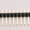
Breakaway Male Headers (Back to list)
The breakaway male header pins are used for three purposes on the Bricktronics Megahield. First, they are used to connect the shield to your Arduino. Second, they are used with the four sensor sockets, to enable the use of the ultrasonic and color sensor (which require slightly-different connections to the sensors). Third, they are used with the motor driver chips to enable you to plug in other motors that are compatible with the voltage and current specifications of the NXT motors, such as the LEGO power functions (PF) motors. You can break them apart with a small pliers.
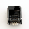
NXT-compatible Socket (Back to list)
To interface with the NXT motors and sensors, we use a custom made NXT-compatible socket that can be soldered right to the Bricktronics Shield PCB. It features the custom offset RJ11-style telephone plug socket port, and will work with the existing cables included with your NXT robotics set. These sockets are also available on their own as Bricktronics NXT-Compatible Sockets, as well as part of the Bricktronics Breakout Board.
Shorting Jumpers (Back to list)
The four sensor ports include a 5-pin header and two shorting jumpers each, to allow the ports to interface with an ultrasonic or color sensor, which require slightly-different connections to the Arduino. The shorting jumpers will connect the two pins it is placed over (hence the name “shorting”), and they are used to selectively connect two pins of each sensor ports to the correct Arduino pins, based on the desired sensor type (button, color, or ultrasonic).