


Design
Some general information about how the LEGO NXT sensors and motors work, and how to work with them using an Arduino.
Contents: Touch Sensor :: Ultrasonic Sensor :: Color Sensor :: LEGO NXT Motors
We also have more detailed pages on the design and theory specific to the Bricktronics Shield and the Bricktronics Megashield.
Touch Sensor
The touch sensor is a button.
Electrical Details and Pinout
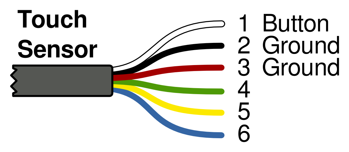
Electrically, pin 1 (connected to the white wire) is connected to the button, and pins 2 and 3 are connected to ground. When the button is pressed, pin 1 is connected to pins 2 and 3 through a resistor.
Ultrasonic Sensor
Ultrasonic sensors work by sending out a pulse of sound that is higher pitched than people can hear. (Although, if you listen carefully, you may be able to hear some clicking when it’s going!) The ultrasonic sensor keeps track of how long it takes for the sound wave to bounce and come back. It uses that time to find out how far away the obstacle is.
This is similar to how sonar and echolocation work.
Electrical Details and Pinout
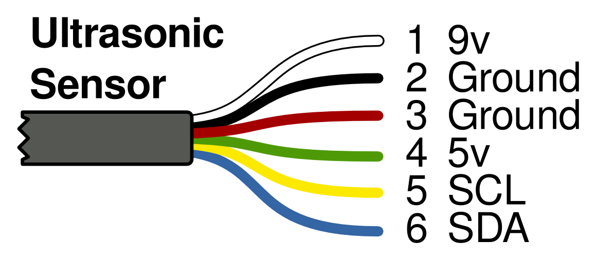
Electrically, pin 1 (connected to the white wire) is connected to 9-7.2V, pins 2 and 3 are connected to ground, pin 4 is connected to 5V, pin 5 is the I2C clock, or SCL, and pin 6 is the I2C data line, SDA.
Because every NXT input line has a series current-limiting resistor, there are weak pullups in each I2C peripheral. We have found that those pullups, in combination with the internal pullups on the Arduino, are enough to provide clean signals at the NXT I2C data rate of 9600 baud.
Communication Details
There are a lot of details about I2C and the Ultrasonic sensor in the LEGO Hardware Development kit, including a full schematic of the NXT brick and the ultrasonic sensor.
The Ultrasonic Sensor uses I2C, a standard protocol for communication between microcontrollers and peripherals–but the Ultrasonic Sensor doesn’t follow the protocol! With a lot of companies, this would presumably be intentional, to make it harder for other people to connect up–but LEGO was kind and open enough to share so much information about the NXT, that we can only assume they made a mistake.
When reading, there needs to be an extra clock.
Thanks go out to TKJ Electronics, who wrote a good blog entry on the Ultrasonic Sensor and its quirks.
We used the SoftI2cLibrary by William Greiman as the base of our Ultrasonic communications inside our Bricktronics library. Thanks William!
Color Sensor
The Color Sensor has an RGB LED and an ambient light sensor. The sensor can be set to read the ambient light, turn on each of the LEDs, or read the color of something positioned in front of it. To read the color, it shines red, green, and blue and reads the reflected light of each of them. The Bricktronics library calibrates and combines those reflected light values and determines teh color.
Electrical Details and Pinout
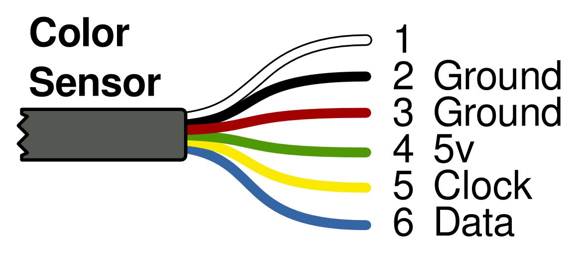
Pin 1 (connected to the white wire) is connected to a resistor (to help the NXT detect if it is plugged in), pins 2 and 3 are connected to ground, pin 4 is connected to 5V, pin 5 is the clock, and pin 6 is the data line. It does not use I2C.
Communication Details
There isn’t any mention of the NXT Color Sensor in the LEGO Hardware Development Kit. We think it was released after the Hardware Development Kit was released. There weren’t many folks online who had tried to connect to it using anything but the NXT brick. Because of that, we didn’t have a schematic, but we did have source code for the NXT, and an alternative firmware for the NXT called leJOS. We also created a cable that let us watch what the wires were doing when the NXT was reading the sensor. Between the source code and spying on the transmissions, we were able to successfully connect the Arduino to the NXT Color Sensor.
There’s a clock and data line, and the master can drive both the clock and data line, and the Color Sensor can drive the data line. When the Color Sensor drives the data line, it can either be an analog voltage or a digital one.
The master initializes the system, telling the color sensor what color it wants the light to be, and the color sensor responds by returning a calibration table. This table has three portions–one when the ambient light is low, one when the ambient light is in the middle, and one when the ambient light is high. These thresholds are sent as well.
When the master wants to take a reading, it toggles the data line, and the sensor responds by reading the ambient light level, and then setting that value on the data line as an analog voltage. The master reads that value, then toggles the clock, which makes the Color Sensor flash the red portion of the LED. It reads the light level, and sets that value on the data line as an analog voltage. The master reads that, and then toggles the clock. The sensor flashes the green portion of the LED, then reads the light level, and sets that value on the data line as an analog voltage. The master reads that, and then toggles the clock. Finally, the sensor flashes the blue portion of the of the LED, reads that light level, and sets the value on the data line as an analog voltage.
The Bricktronics library then sets those raw values into the raw_values array. The calibrate function does the same thing the NXT does–it looks at the ambient value, and then picks which calibration table to use based on the limits the sensor sent. It takes each value from raw_values, calibrates it, and then puts it in cal_values. The cal_to_color function takes those calibrated values from cal_values, and comes up with an answer of black, white, red, yellow, blue, or green. It’s taken from leJOS, which took it from the newest version of the NXT firmware. It works well for reading LEGO brick colors, but for other things, you may want to use cal_values directly. If you come up with a better cal_to_color function, let us know!
5V Tolerance
We took the Color Sensor apart to try to find out if we could use 5V logic, or if we had to stick to 4.3V. There are three connections going into the sensor: Vcc, clock, data, and ground. Ground doesn’t change. Vcc powers an ATtiny13A, which is 5V tolerant. The clock line is always driven by the master (usually the NXT). The NXT drives it between 0 and 3.3 volts or so. Tracing the clock line on the PCB, it goes directly into a pin on the ATtiny13A, which will be fine with 5V logic when powered at 5V. The data line is sometimes driven by the master, and sometimes driven by the Color Sensor. It is always a digital signal when driven by the master, and sometimes digital and sometimes analog when driven by the Color Sensor. Tracing out the PCB trace, there doesn’t appear to be any issues with 5V vs 4.3V or 3.3V. Lastly, there are the LEDs. The LEDs were a concern–driving LEDs with too much current can reduce their life. When the Color Sensor was being driven by an NXT, the voltages on the red, green, and blue lines were 2.0V, 3.2V, and 3.5V respectively. When the Color Sensor was being driven by 5V logic using the Bricktronics library, the voltages on the red, green, and blue lines were 2.12V, 3.28V, and 3.7V respectively. This is only a little more voltage than you’d get by natural variation on the current-limiting resistors, and the individual LEDs aren’t even on all the time. By having the LEDs turn on and off, the average current drops. Wheew!
LEGO NXT Motors
LEGO NXT motors contain a DC motor that has been geared down 48:1, an optical encoder, and a PCB.
Two of the connection signals drive the motor. When one wire is 9V more than the other, the motor drives the orange hub full speed one way. When the other wire is 9V more than the first, the motor drives the orange hub full speed the other way. By applying an intermediate voltage between the wires, slower speeds can be achieved. By using pulse-width modulation, or PWM, allows the motor to have full torque at the lower speeds and is the recommended way to drive the motor.
Optical Encoder
The LEGO NXT motor also has an optical encoder, in order to keep track of the position. This allows the LEGO NXT motor to benefit from feedback.
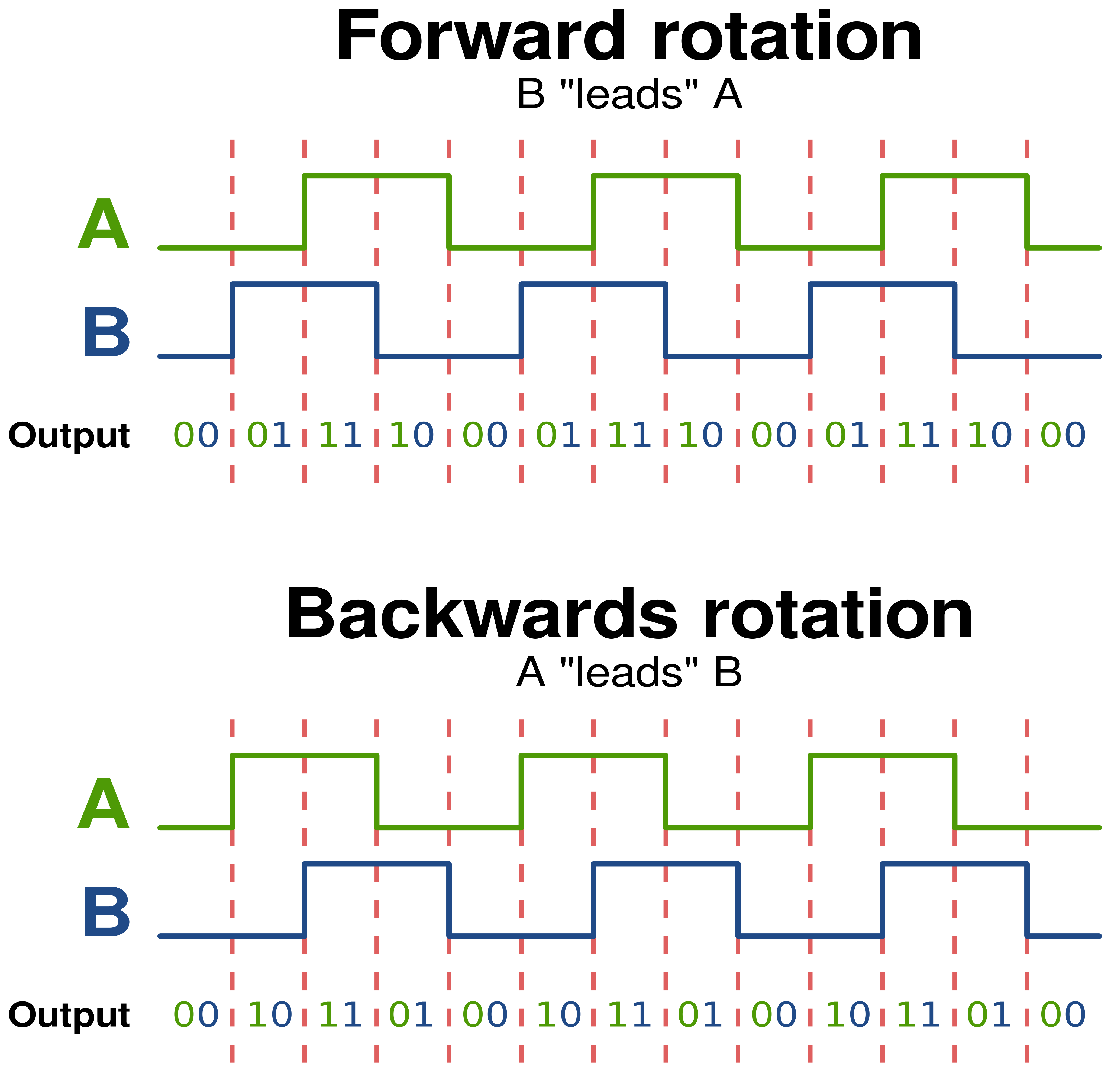
An optical encoder consists of a circle of black plastic with slots cut in it. Two optical forks are mounted over the circle, and can tell when the slots pass through the beam. Because there are two sensors inside the fork, it can also tell which direction the circle is rotating. The PCB has some circuitry on it that protects the motor and cleans up the optical encoder signals. These clean signals are provided as two outputs on the NXT motor connector. Each line has two states, either “optical beam blocked†or “optical beam not blocked.†Our Bricktronics library watches these signals, and keeps track of the relative motion.
More information
Philo has collected an overwhelming amount of information on the NXT motors at his site.
Note: Wayne and Layne, LLC and our products are not connected to or endorsed by the LEGO Group. LEGO, Mindstorms, and NXT are trademarks of the LEGO Group.