


Design
Looking for the hardware design files? The schematic and much more is available at the download page.
It is not necessary to understand every part of how the Video Game Shield works to play or make video games for the Arduino. However, knowledge is power!
There are two main aspects of the Video Game Shield: the video interface and the Nunchuck interface.
The Video Game Shield schematic will be useful when reading about the design of the kit. The rest of the design files are available as well.
Video Generation
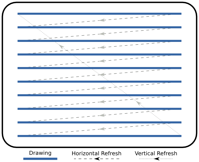
Black and white analog broadcast television is relatively simple. In an old TV, an electron gun is used to draw a static image across a display, line by line, top to bottom. The gun is stationary, and the beam of electrons is directed using magnetic fields. When the beam of electrons reaches the end of the display, the next picture is drawn, line by line, starting at the top. The individual horizontal lines are called scanlines and each picture is called a frame. There is a delay between the time when the electron beam reaches the last part of a line and moves all the way back to the start of the next line. This is called the horizontal refresh. There is also a delay between the time the beam reaches the end of the frame and has to be guided back to the top of the screen for the next frame. This is called the vertical refresh or vertical blanking interval. Over the years, various standards have used the vertical blanking interval to transmit extra data in a mostly backwards compatible way. This extra data includes color, and closed caption text.
All current analog television schemes are interlaced. Interlacing video means to split each frame into two parts–the even numbered lines and the odd numbered lines, and show them sequentially. Interlacing has some trade offs, but increases the effective resolution of video.
There are a variety of world standards for frame rate, or the number of frames shown per second, and specific voltages. The two most common broadcast television standards are NTSC and PAL.
Black and white analog broadcast television consists of a single analog voltage varying over time. If we create an analog voltage and time it just right, we can draw black and white pictures on a television. Granted, we have to be quick about it, but we can do it. The “normal” way of creating analog voltages on an Arduino is called pulse width modulation, or PWM.
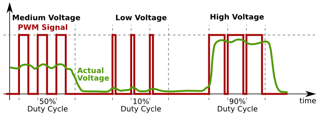
This is what happens when you use analogWrite. Unfortunately, the Arduino’s pulse width modulation isn’t fast enough for our needs, so we can’t use analogWrite. To create a black and white signal, we need to be able to output three voltages:
- 0 volts, for the synchronization pulses
- 0.3 volts, for the black parts of the image
- 1 volt, for the white parts of the image
We can do this with two pins and two resistors:
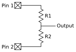
This is a very common circuit fragment, and is given a special name: a voltage divider.
If the two resistors were identical, the voltage of the node in between the two pins with respect to ground would be exactly in the middle of the voltages of the two pins. If the first pin was 5 volts and the second pin was 0 volts, the middle node would be at 2.5V. This comes from Ohm’s law. The same amount of current is going through each resistor. Why? Where else would the current go when it goes down one side *besides* right up the other side? Because the voltage across a resistor is the product of the current through that resistor and the resistance of the resistor, the voltage across each of the identical resistors would also be identical. Similarly, if the first pin was 5 volts and the second pin was also 5 volts, the intermediate node would also be at 5 volts.
We can vary the ratio of the resistances of R1 and R2 to get our desired voltage levels. If R1 was twice the resistance of R2, and pin 1 was at 5V and pin 2 was at 0V, the common node would be 1/3rd of 5V, or about 1.6 volts. Similarly, if we reversed the pins, and pin 1 was now at 0V and pin 2 was now at 5V, the common node would be 2/3rds of 5V, or about 3.3 volts.
We’re going to need something else to get this to work. There’s a hint in the question two paragraphs above. When we attach this middle node to a television input, the television input isn’t going to act like a multimeter, which doesn’t (or shouldn’t!) affect your circuit. By hooking up the television, we’re going to introduce another resistance in the mix.
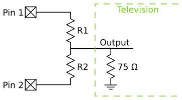
This extra resistor loading enables us to generate the voltages we need. In the drawing below, we try all combinations of 0 volts and 5 volts on the two pins driving the voltage divider and the television.
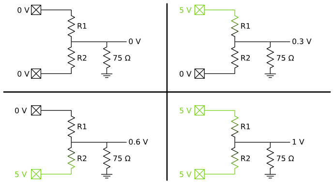
Using two resistors and two pins, the appropriate voltage levels can be created. However, the timing is still tricky.
Thankfully, this has been done for us, in an awesome library called TVout, written by Myles Metzler. This library uses a timer interrupt to switch our two pins at the appropriate time to create analog television signals. If we write code without interrupts, we can edit a big array in memory that represents the screen. During the execution of our code, the timer interrupt goes off and our code is paused while the TVout library outputs the analog voltages needed by toggling those two pins at the right time. It returns to our code during the refresh periods of each frame.
Audio
The audio from Video Game Shield is mono, one bit audio. It is generated in software in TVout’s library using code very similar to that of Arduino’s tone(). The square wave is sent through a voltage divider to reduce the range from 0 to 5V to below the line-level input requirements of 2 volts peak to peak. There’s also a DC blocking capacitor to help reduce noise and “hum”.
Nunchucks
The Wii Nunchuck communicates with the Wii Remote using a protocol called I2C. I2C is a common way to hook other smart things to a microcontroller. It uses two signals lines: one for the clock, and one for the data. Devices can be a master or a slave device, and every device has an I2C address. This address is used to communicate between devices, as more than just one master and one slave can be connected to the same I2C bus at the same time. I2C can be run at different voltages, and both 5V and 3.3V are common.
The Wii Remote is a master on the I2C bus, and the Nunchuck is a slave. All the Nunchucks in the world have the same I2C address of 0, which presents a problem. One of the requirements when designing the Video Game Shield was support for multiple players. Normally, with I2C, multiple devices on a bus are no problem. When requesting data, you include the address of the device to get the data from, and only the appropriate device responds. However, with every Nunchuck having an identical address, we needed an alternate way to connect both Nunchucks to the Arduino. We turned to a bidirectional switch chip, the 4066. The chip has 4 sets of paired terminals with enable lines. When the enable lines are set high, the two pins are electrically connected and our data can pass through. When the enable line are set low, the two pins are electrically disconnected. By setting the appropriate enable lines, we can connect one Nunchuck to the Arduino, request all the data from the Nunchuck, receive the data, and then change the enable lines to connect the other Nunchuck to the Arduino.
To make this work, we need to connect the enable line to the Arduino. The simplest way would be to connect each of the four enable lines (clock and data for each Nunchuck) to a different Arduino pin. We could include a library function that would toggle the appropriate pins at the right times, and everything would work. This would use four pins, and if we have a bug in our program, or someone decides not to use our library, things could get pretty weird. If you forgot to initialize those pins, no Nunchuck would be connected, and if you enabled all four lines, both Nunchucks would be connected at the same time. While this is simple on the hardware side, this sounds pretty horrible on the software side. To simplify things, we look more closely at how things will work.
We never want to connect the clock of one Nunchuck to the Arduino at the same time as the data of the other Nunchuck, so we can reduce the number of pins used by simply making one pin on the Arduino connect to the enable lines of both the clock and data of a particular Nunchuck. This reduces our Arduino pin count to two, but still leaves us with the software issues and the potential for very confusing situations.
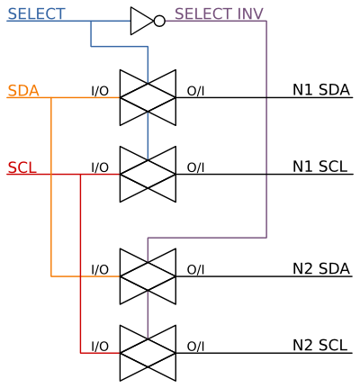
Considering our previous idea with just two pins, we want each of the pins to be the opposite of the other. If we have our first Nunchuck enabled, we always want the second Nunchuck to be disabled. If we want the second Nunchuck enabled, we always want the first Nunchuck disabled. This is a NOT relationship, and we can do this with an inverter. We connect one pin on the Arduino to one Nunchuck’s enable lines (Nunchuck 1), and connect that same pin to an inverter. The output of the inverter is connected to the other Nunchuck’s enable pins (Nunchuck 2).
A single transistor can be used to create an inverter. This can be seen around transistor Q3 in the schematic, and in the image below. When the transistor input is at 0 volts, the transistor is off (not conducting electricity) and the pull-up resistor pulls the output voltage up to 5 volts. When the transistor input is at 5 volts, the transistor is on (conducting electricity) grounding the output voltage to 0 volts.
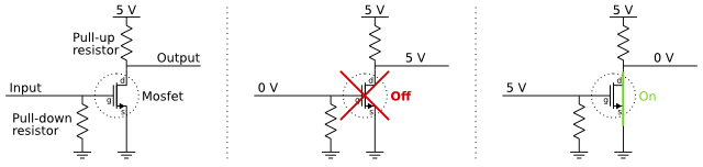
There are two resistors in this MOSFET-inverter arrangement. The pull-up resistor is used to create the inverter, while the pull-down resistor is used to provide a default for the shield. It pulls down the input to the inverter, so if the input to the inverter isn’t set by the microcontroller, the inverter will produce a consistent value, connecting Nunchuck 1 to the Arduino.
The second design issue with connecting Nunchucks to an Arduino is a voltage issue. The Arduino runs at 5 V. The Nunchuck runs at 3.3V. In our experimentation, the Nunchuck will work just fine when powered by 5V, and produces a 5V I2C signal as expected, but when the Nunchuck is “in the wild” and connected to a Wii remote, it is powered by 3.3V. We’d like to avoid any unfortunate situations where our shield wreaks havoc on someone’s Nunchucks, so we’ve designed the Video Game Shield to also run the Nunchuck at 3.3V. This means the I2C digital signal switches between 0V and 3.3V.
When the Arduino is powered by 5V, the Atmega328p datasheet says that the input pins will recognize a 3V signal as a logic HIGH. Since this 3V threshold is below the 3.3V output from the Nunchucks, everything should work fine, right? Unfortunately, when adding up the tolerances between the 3.3V regulation on the FTDI chip and the unknown tolerances of the Nunchuck, it’s possible that the Arduino doesn’t reliably read the data from the Nunchuck. To fix this, we need something to put in between the Arduino and the Nunchucks to convert the “0 to 3.3V” signal from the Nunchucks into the “0 to 5V” signal needed by the Arduino.
While we could use a dedicated chip for this, we can also use a single MOSFET for each signal line to do the bidirectional level shifting. This is described by the Phllips corporation in Application Note AN97055 Bi-directional level shifter for I2C-bus and other systems.
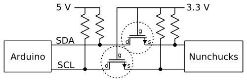
There are basically three states here (paraphrased from section 2.3.1 of the application note).
- The first state is that no devices are pulling down the line. This means that both the gate and the source will be at 3.3V. Because of this, the transistor is turned off, so the 5V side of the line is pulled up by its pull up resistor to 5V. Both sides are at their respective HIGH voltages.
- The second state is that the 3.3V side pulls down the line. The source is now near ground, and the gate is at 3.3V. The transistor turns on. The 5V side is pulled down towards ground. Both sides are LOW.
- The third state is that the 5V side pulls down the line. The 3.3V side gets pulled down a bit through the drain-substrate n-p junction (diode), and then the MOSFET turns on. Now the 3.3V side gets pulled down to LOW through the conducting MOSFET. Both sides are now LOW.
Pretty awesome, huh?
This is done in our schematic with Q1 and Q2.
The third issue with the Nunchucks is minor–the Wiring I2C library uses interrupts in a way that is incompatible with the TVOut library. To work around this, we used Peter Fleury’s open source I2C library that uses polling. We made some changes to enhance usability.