Build Instructions, Short
These are the abbreviated instructions for people with prior soldering experience. Here are the full build instructions.
Step 0: Gather Tools
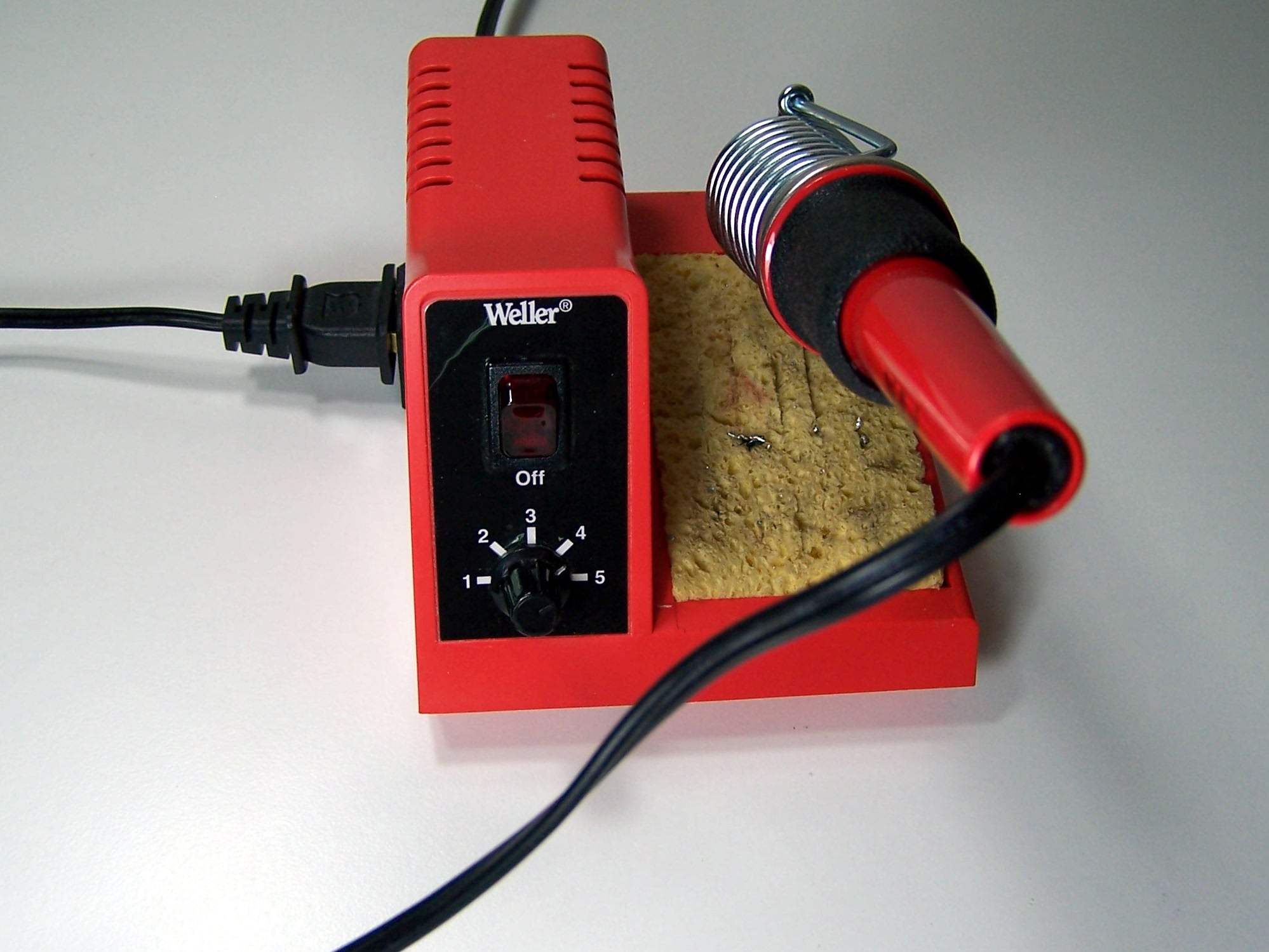
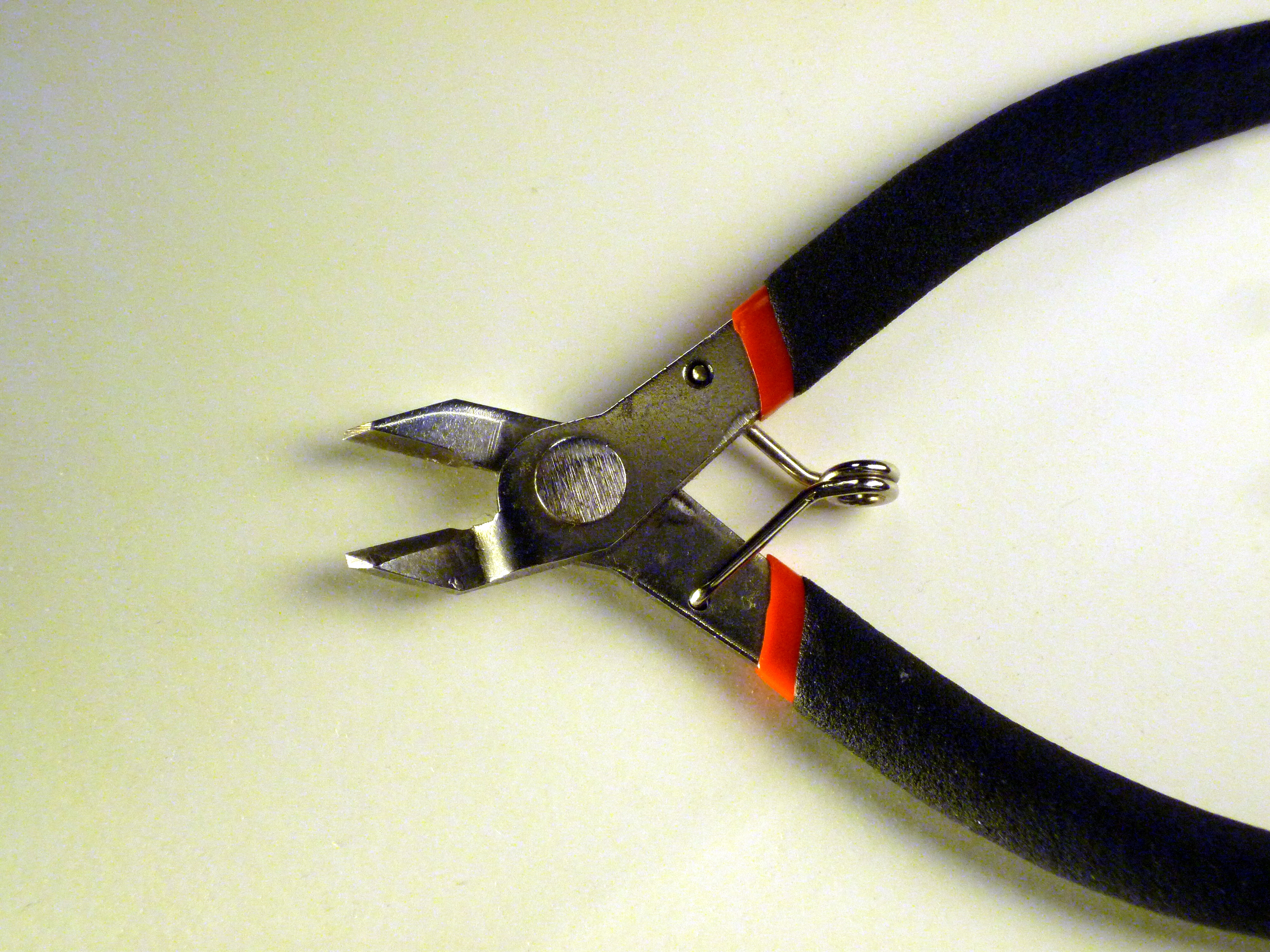
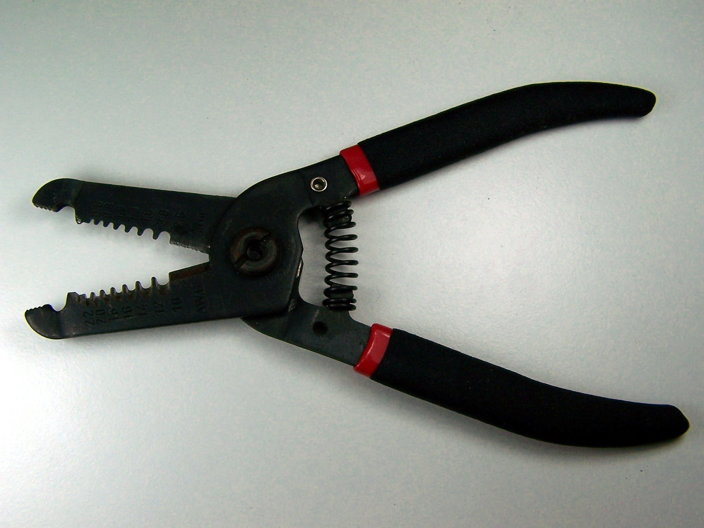
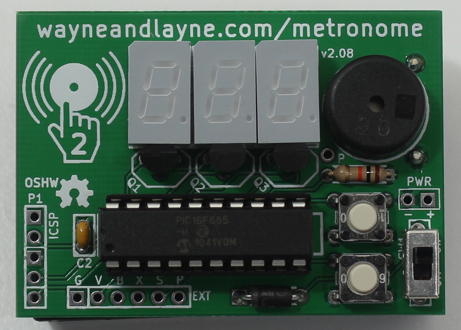
Step 1: Part Identification
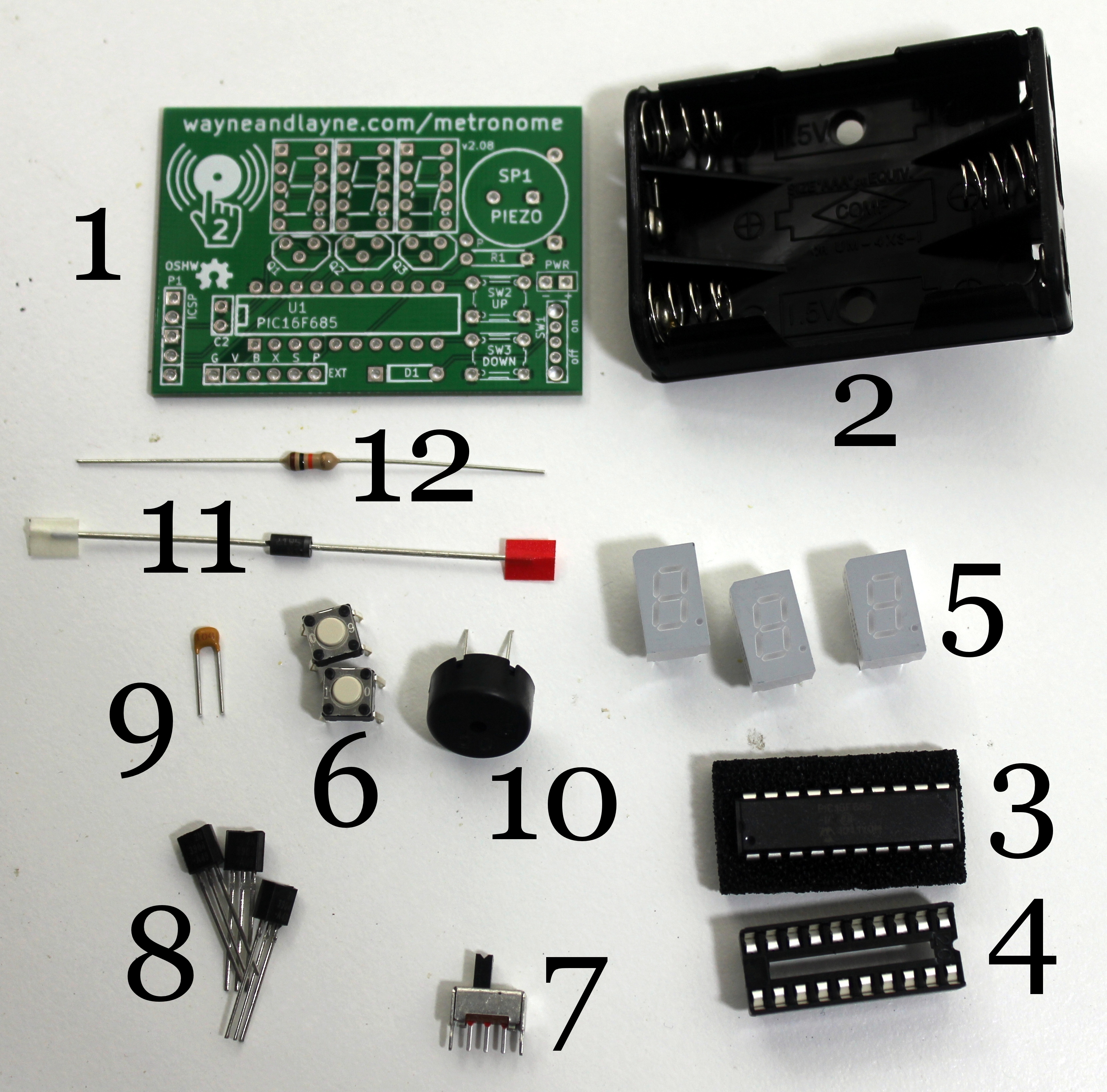
Open the bag of parts, and make sure you have all of the parts listed below. It might be easier to lay them out as shown in the picture. Click to enlarge.
Step 2: Push Buttons – Push them into SW2 and SW3.
Step 3: Seven Segment Displays – Solder one pin each, first, then check alignment.
Step 4: Transistors – Three transistors labeled Q1, Q2, and Q3. Align the flat side towards the display.
Step 5: Ceramic Capacitor – Unpolarized, labeled C2 on the PCB.
Step 6: Chip Socket – Solder one pin first, labeled U1. Align notch in socket with notch on PCB drawing.
Step 7: Resistor and Diode – Resistor is unpolarized, labeled R1. Align silver stripe of diode with thick white line on PCB (next to square pad), labeled D1.
Step 8: Power Switch – Power switch SW1, unpolarized.
Step 9: Piezo Buzzer – SP1, make sure it’s flat on the board.
Step 10: Review – Trim all the leads, measure huge resistance across battery terminals to check for shorts.
Step 11: Insert Processor Chip – Bend the leads in a bit and insert the chip into the socket. Be sure to align the notch in the chip with the notch on the PCB.
Step 12: One Final Test – Put batteries in the holder and insert it through the holes and twist to make contact. Listen for beeps, try tapping it, make sure the displays and buttons work.
Step 13: Battery Holder – Be sure to trim down the previous components’ leads. Attach foam tape, peel off other side. Press against the PCB and solder down the leads.
Step 14: Completion! – Give the completed board a final look over, checking for loose solder connections or shorted pads. Congratulations! You’re now the proud owner of a Tactile Metronome. Install some AAA batteries and give it a try!