


Build a Blinky Kit!
These instructions are for building a through-hole Blinky kit.
The instructions for the surface mount Blinky SMT kits are over here!
These are the building instructions for the Blinky GRID and Blinky POV kits. Because they are so similar, the building instructions are combined together into one document. Even though the photographs show a Blinky GRID circuit board, the Blinky POV circuit board is identical (aside from the number of LEDs), so all components are placed in the same positions for both GRID and POV PCBs.
Step 0: Gather Tools
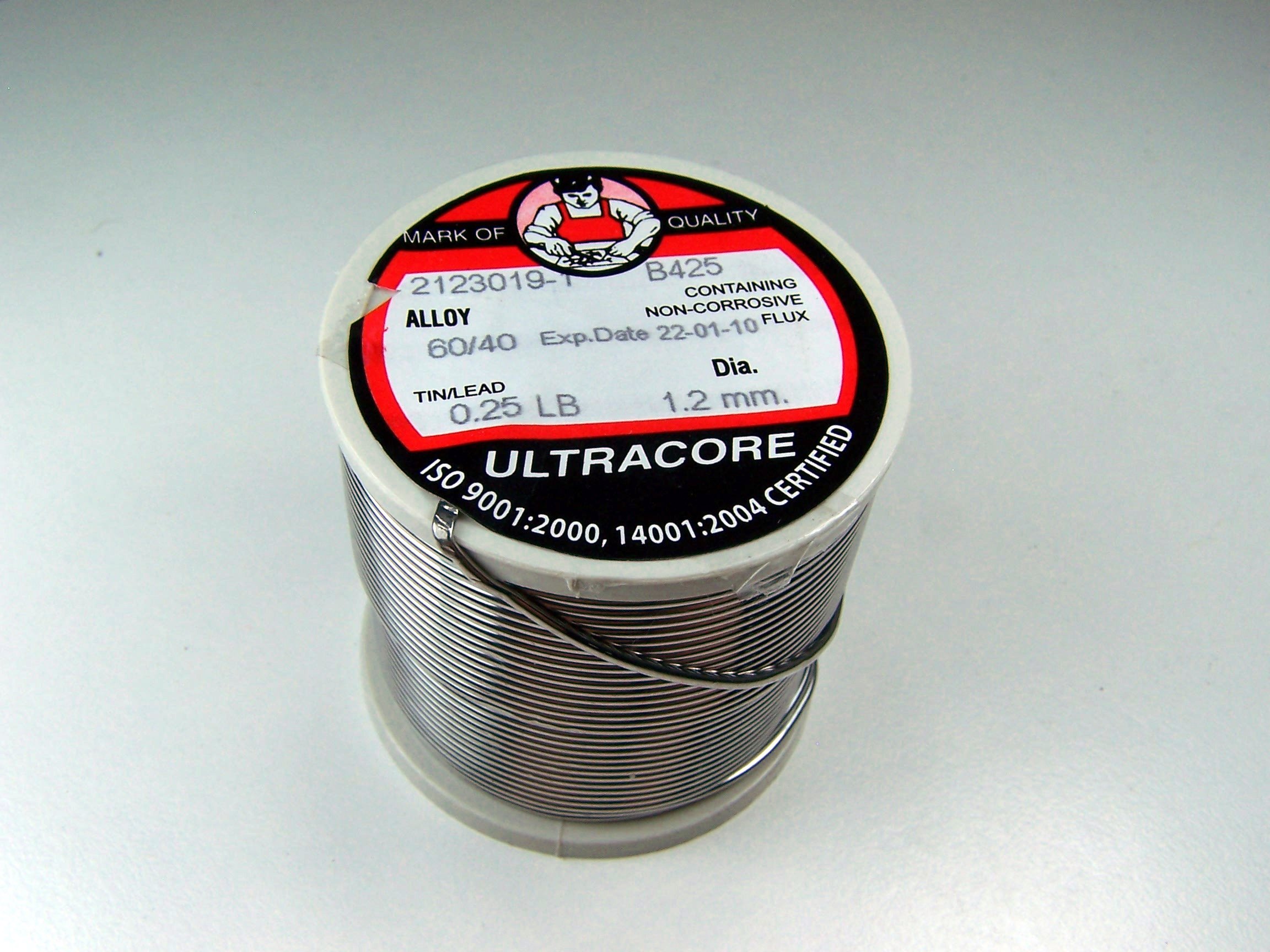
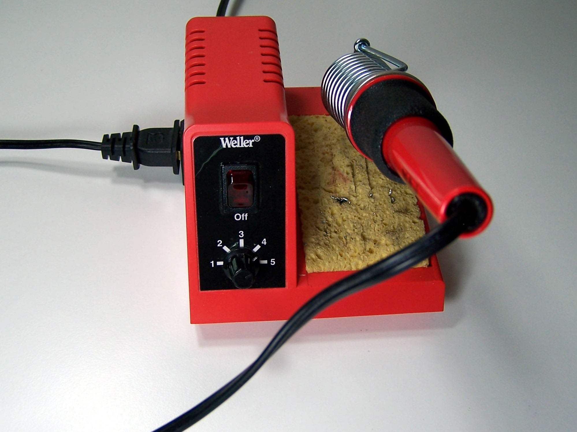
To build the kit, you will need a few common tools for soldering and electronics work. A soldering iron and solder are the most important tools. You can use any soldering iron, although a higher-quality, temperature-controlled adjustable iron will be easier to work with and give higher quality results. Any standard solder for small electronics will do just fine.
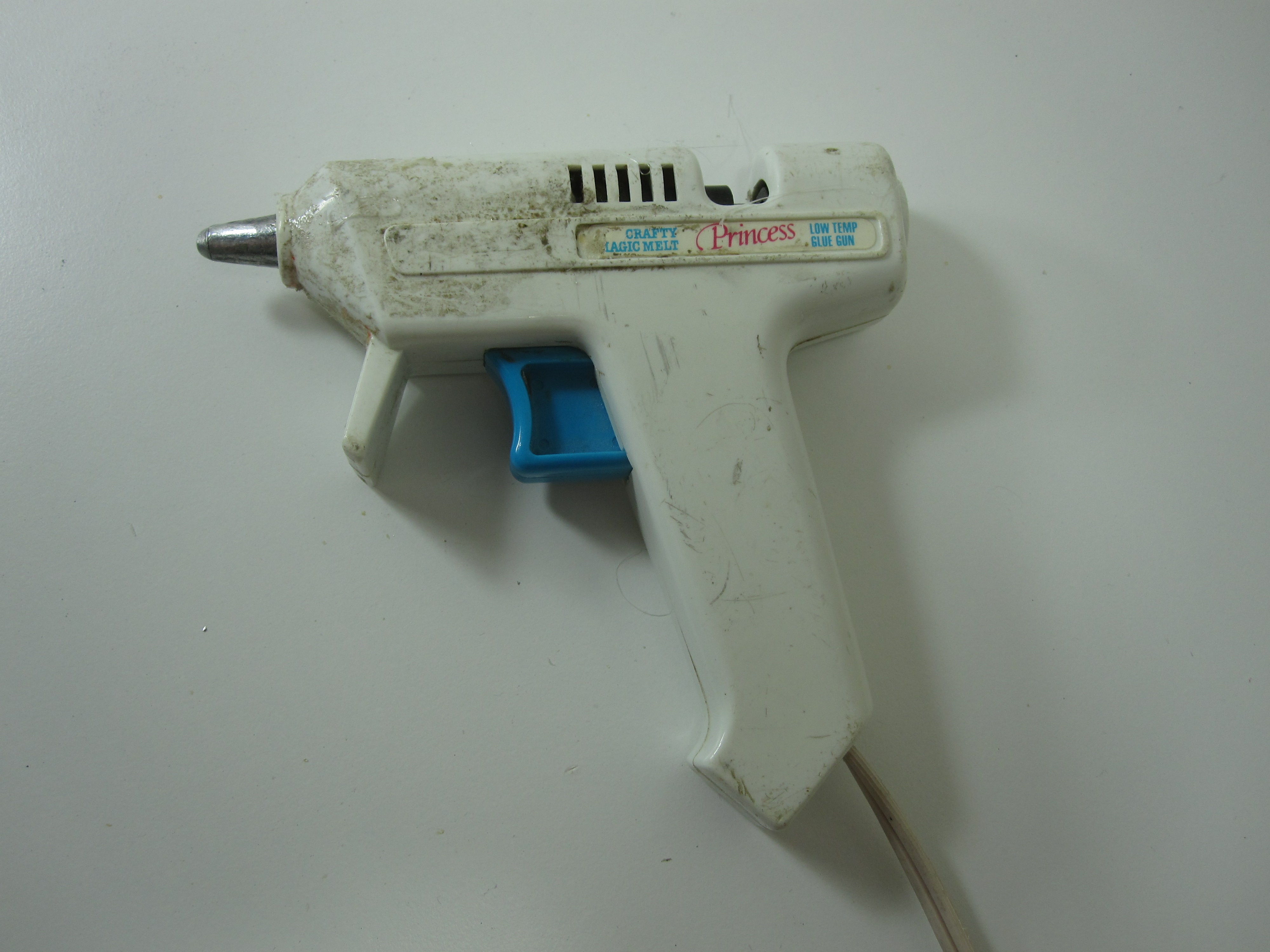
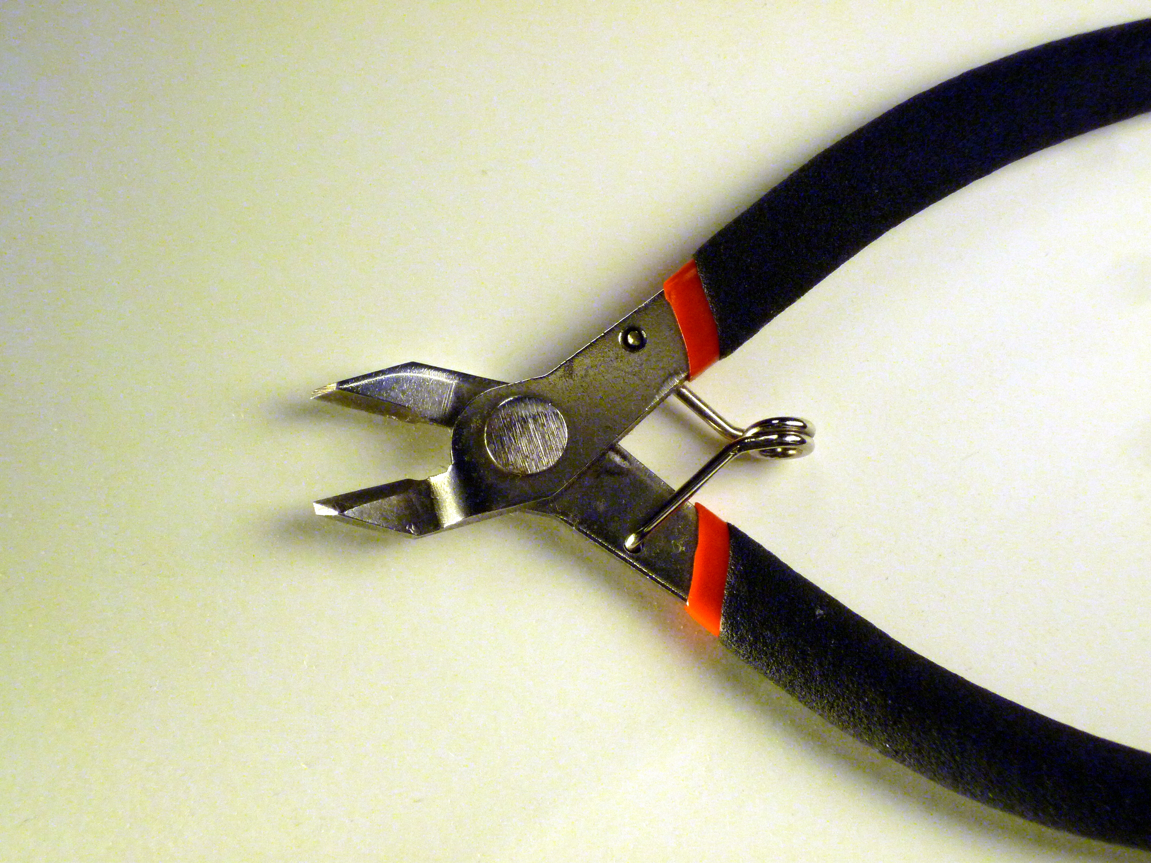
To trim the extra leads on the bottom of the pcb a diagonal pliers will work very well. A hot glue gun could be useful in the final steps to secure the PCB to the battery holder.
If you need some additional guidance and instruction on soldering, SparkFun, NASA, and Curious Inventor all have quality soldering tutorials.
Step 1: Part Identification
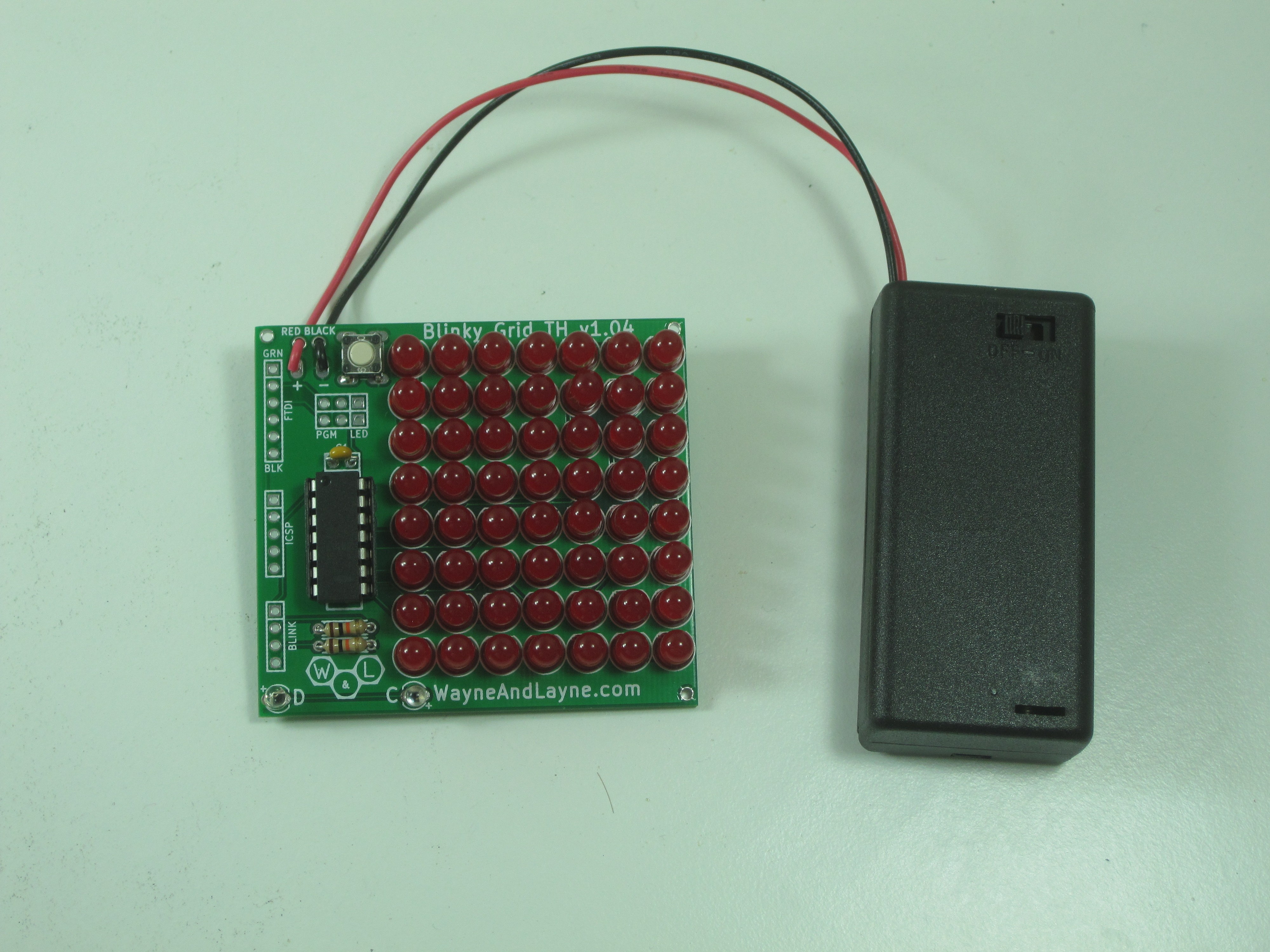
Open the bag of parts, and make sure you have all of the parts listed below. It might be easier to lay them out as shown in the picture. If you have the Blinky POV kit, you have a different circuit board and won’t have as many LEDs, but should still have all the other parts in the same quantities. Click to enlarge.

- (1) Blinky GRID/POV Printed Circuit Board
- (1) 2xAA Battery Holder
- (8/56) Light Emitting Diodes (LEDs)
- (1) 14 pin chip socket
- (1) PIC 16F1823 Microcontroller
- (2) 10k resistors
- (2) Ambient Light Sensors
- (1) 0.1 uF ceramic capacitor
- (1) Pushbutton switch
This kit is easy to solder, and shouldn’t take too long. We’ll start with the easiest parts, and work our way to the more complicated parts. The general plan is to solder in the shortest parts first, and the tallest parts last.
Some parts are polarized, and have to go in the board a certain way, but also some parts are not polarized. In the steps to follow, if a part is polarized, we will mention which way it must be installed. The PCB is also marked to identify the polarization.
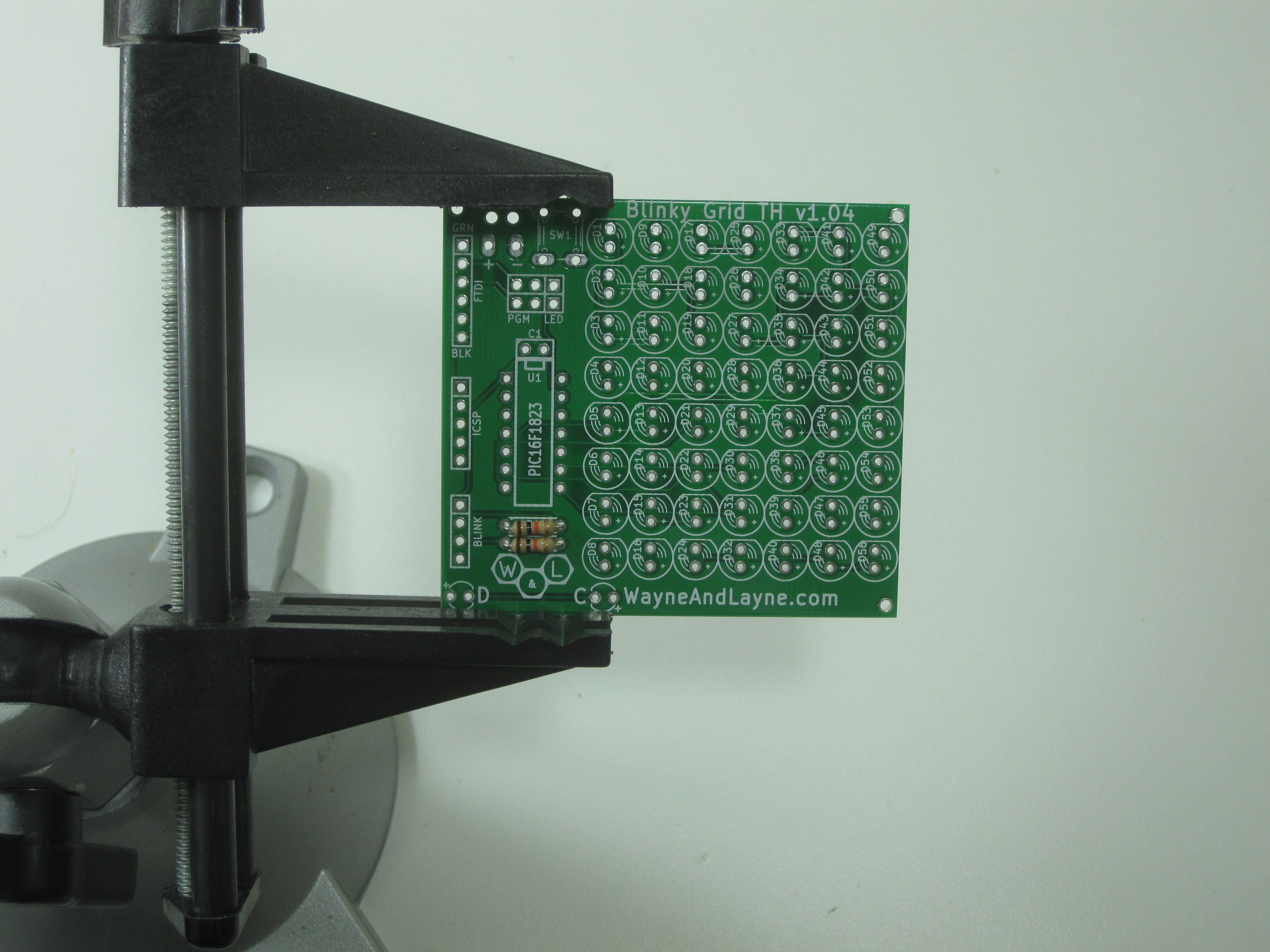
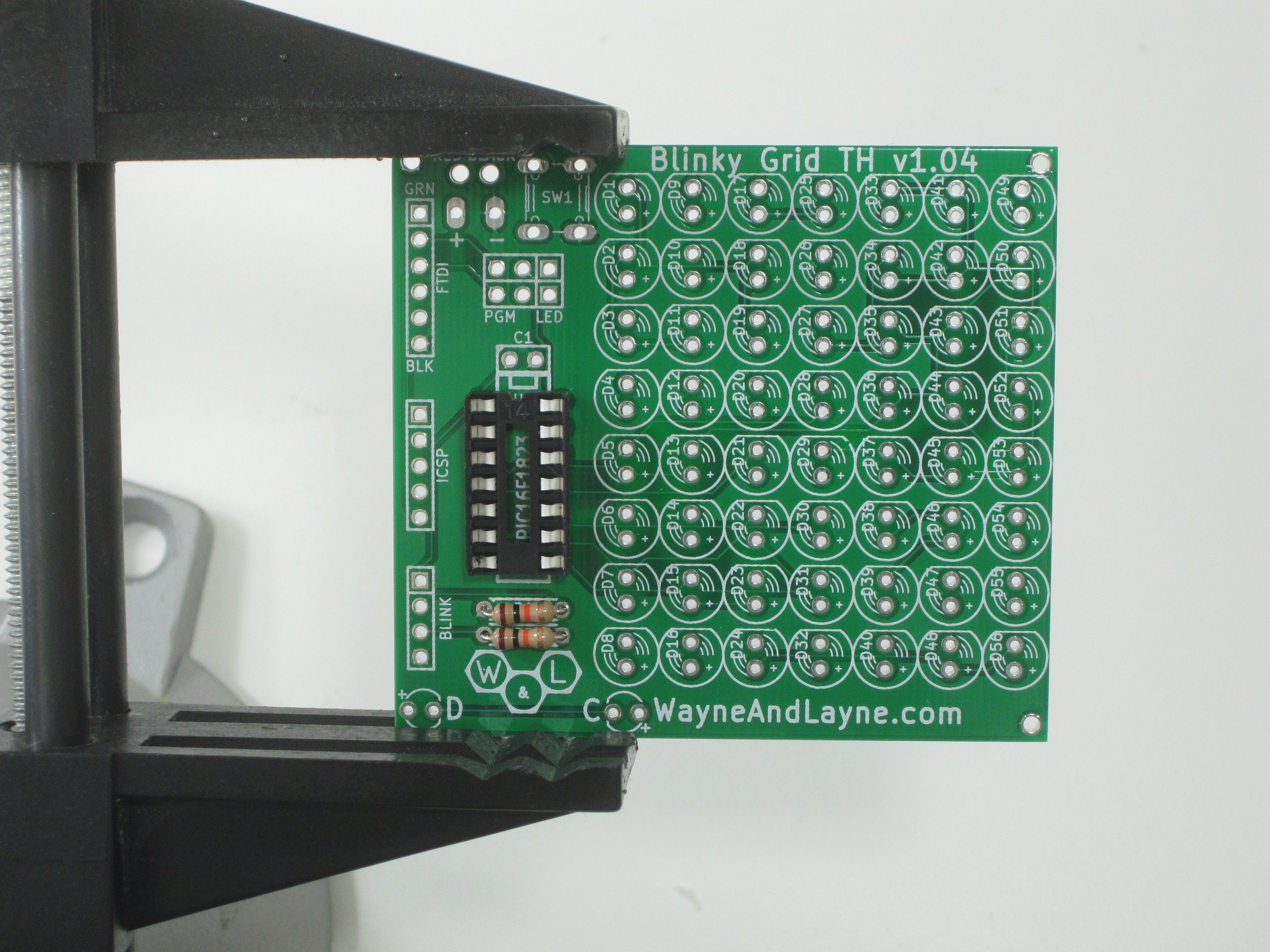
Step 2: 10k ohm resistors
Resistors are easy to solder, so start with this pair of 10k ohm resistors. They are marked with Brown-Black-Orange colored bands. Bend the leads so the resistors fit into the marked locations (R1 and R2) on the board. Resistors are not polarized, so they don’t have to go in a certain way. To solder things with long legs like this, you can turn the board over and bend the legs a little bit, so the component doesn’t fall out while the board is upside-down.
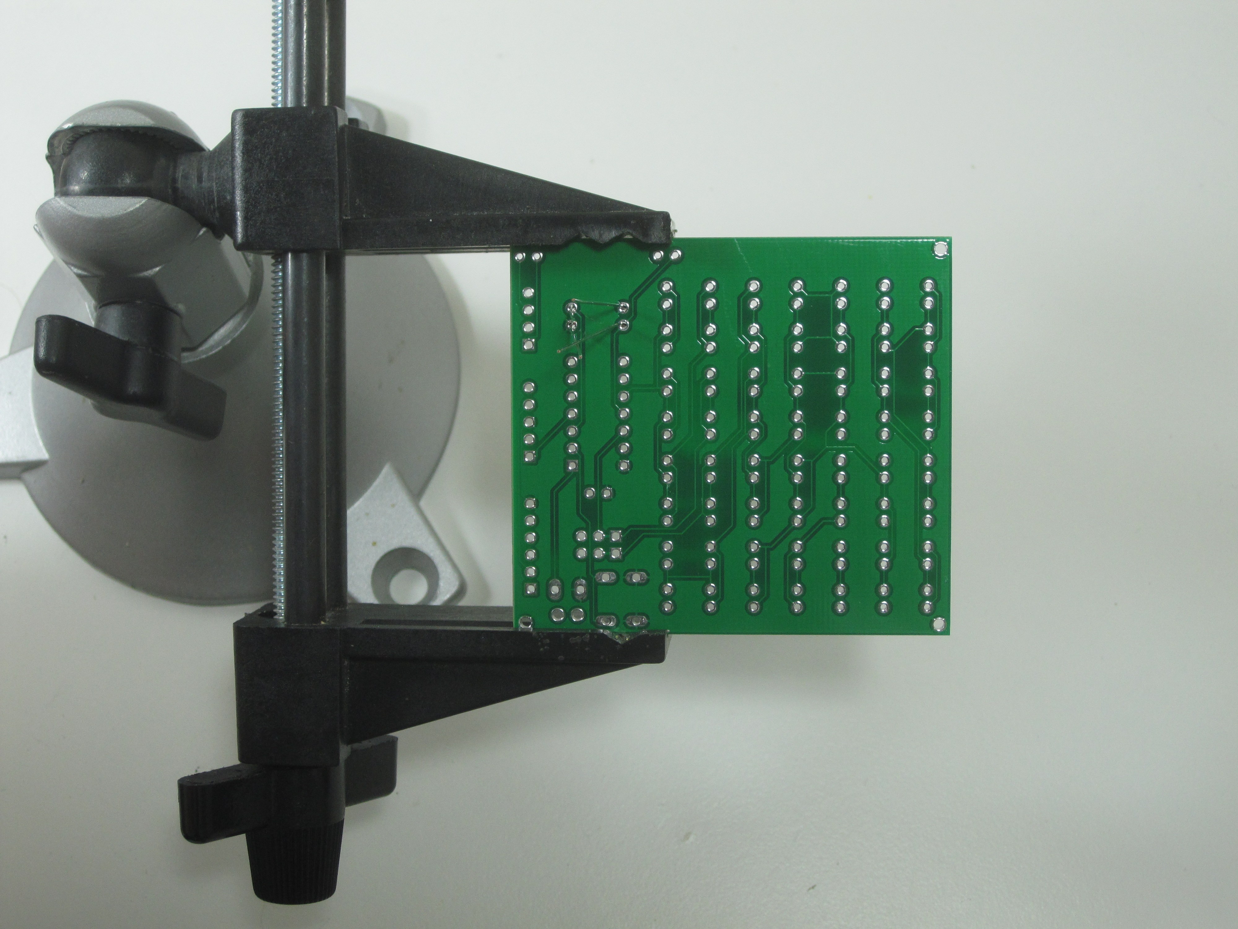
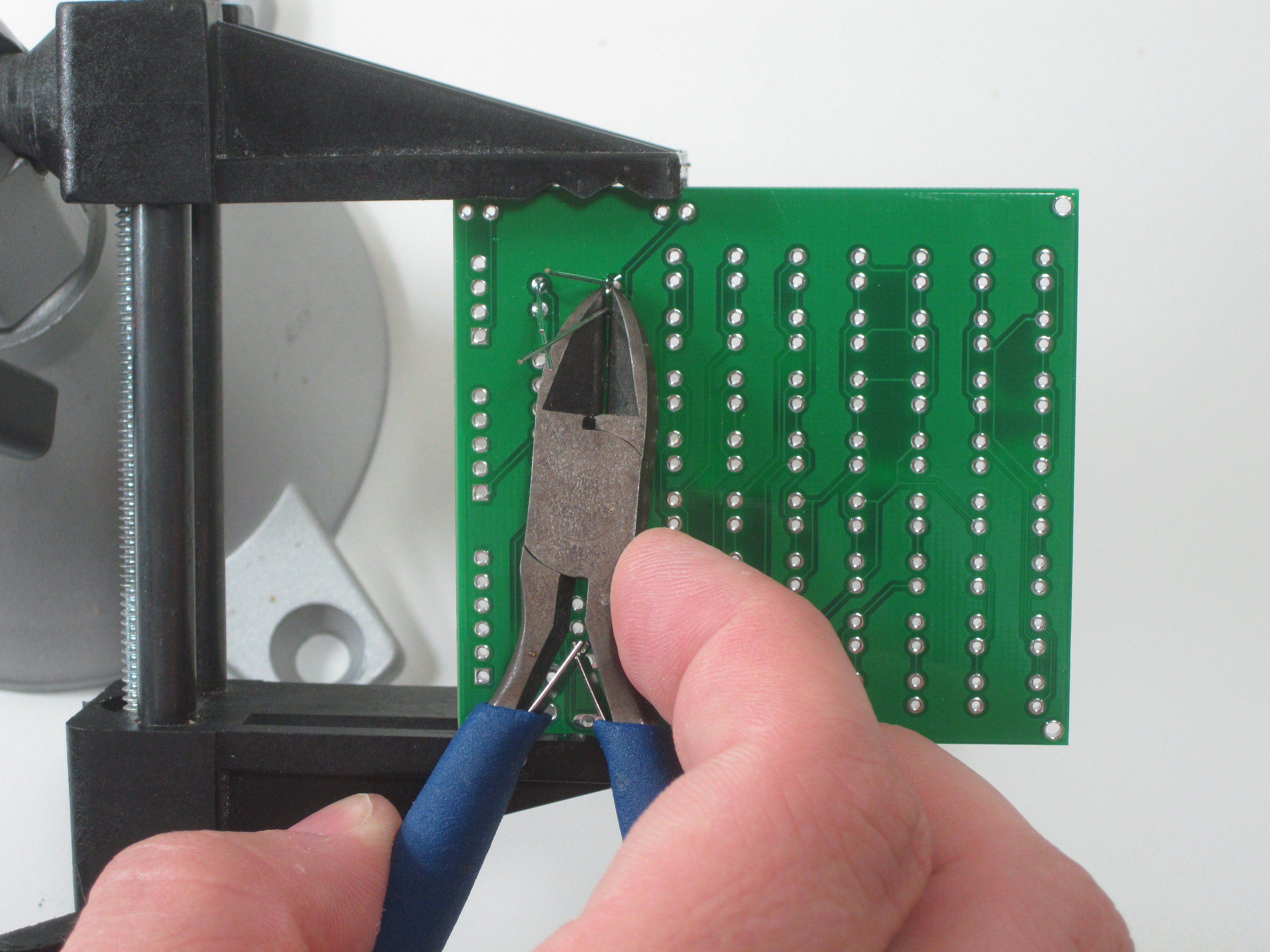
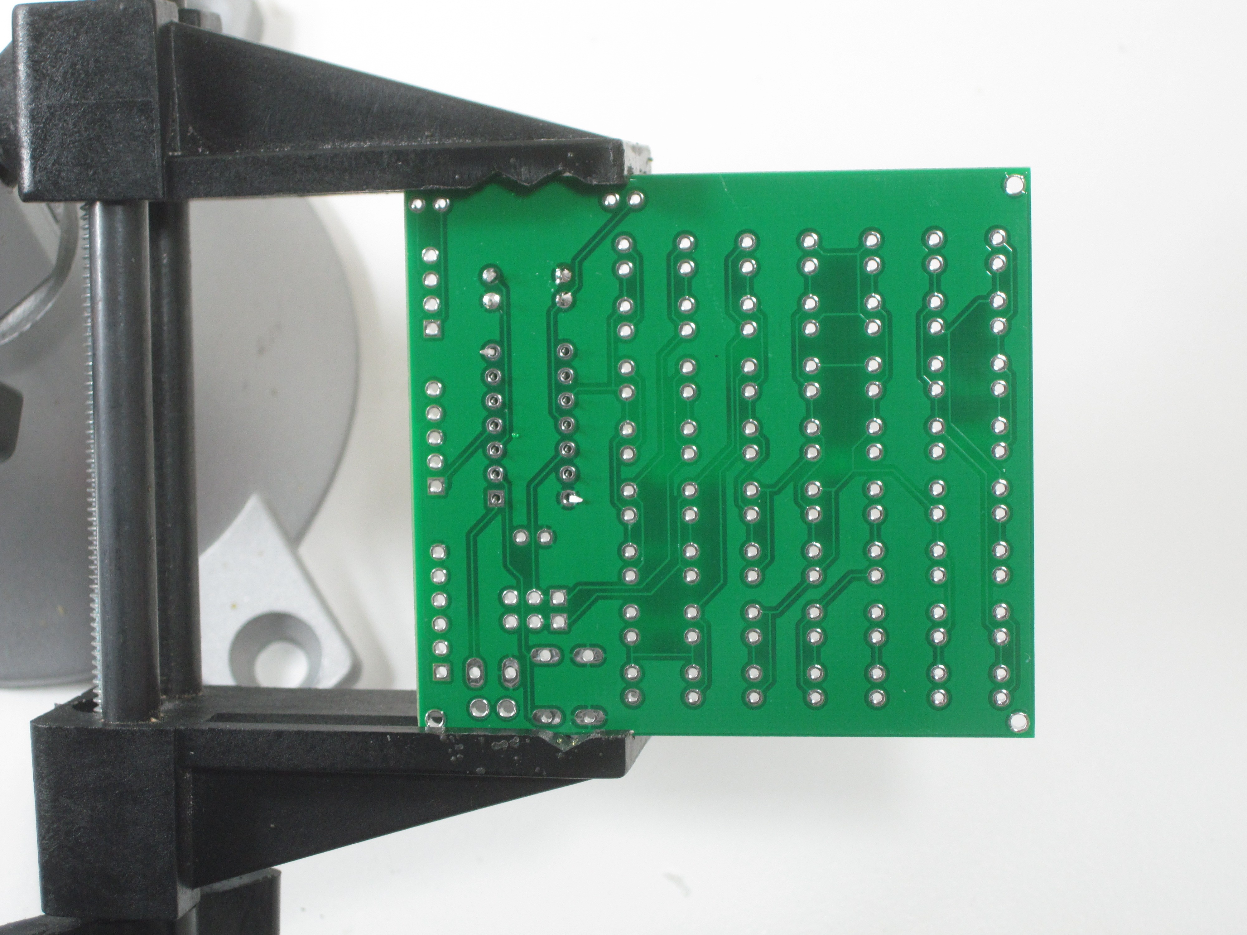
Use your soldering iron to heat up one leg of the first resistor and the ring around the hole at the same time. Push a little bit of solder on the ring. The solder should melt and flow around the hole. If you’re having trouble, make sure the tip of your iron is tinned and shiny. Remember to heat up the pad and the pin, and you don’t need to apply a lot of solder. Don’t try to use the iron like a paintbrush. Use the diagonal clippers to trim the legs of the resistors, down to just above the solder joints.

Step 3: Chip Socket
Insert the socket into the board. The footprint on the board is labeled U1. There is a notch in one end of the socket that should line up with the notch in the drawing on the PCB, next to the ceramic capacitor (C1). It usually helps to bend one of the legs to keep the socket in place while soldering. Take care to ensure that the socket is flush against the PCB while soldering, because it can be difficult to insert a chip into a crooked socket. You might want to solder only one pin at first, and then check the alignment. If the socket is crooked, you can melt that pin’s solder and push the socket into place. Once it is aligned, solder the rest of the socket’s pins.
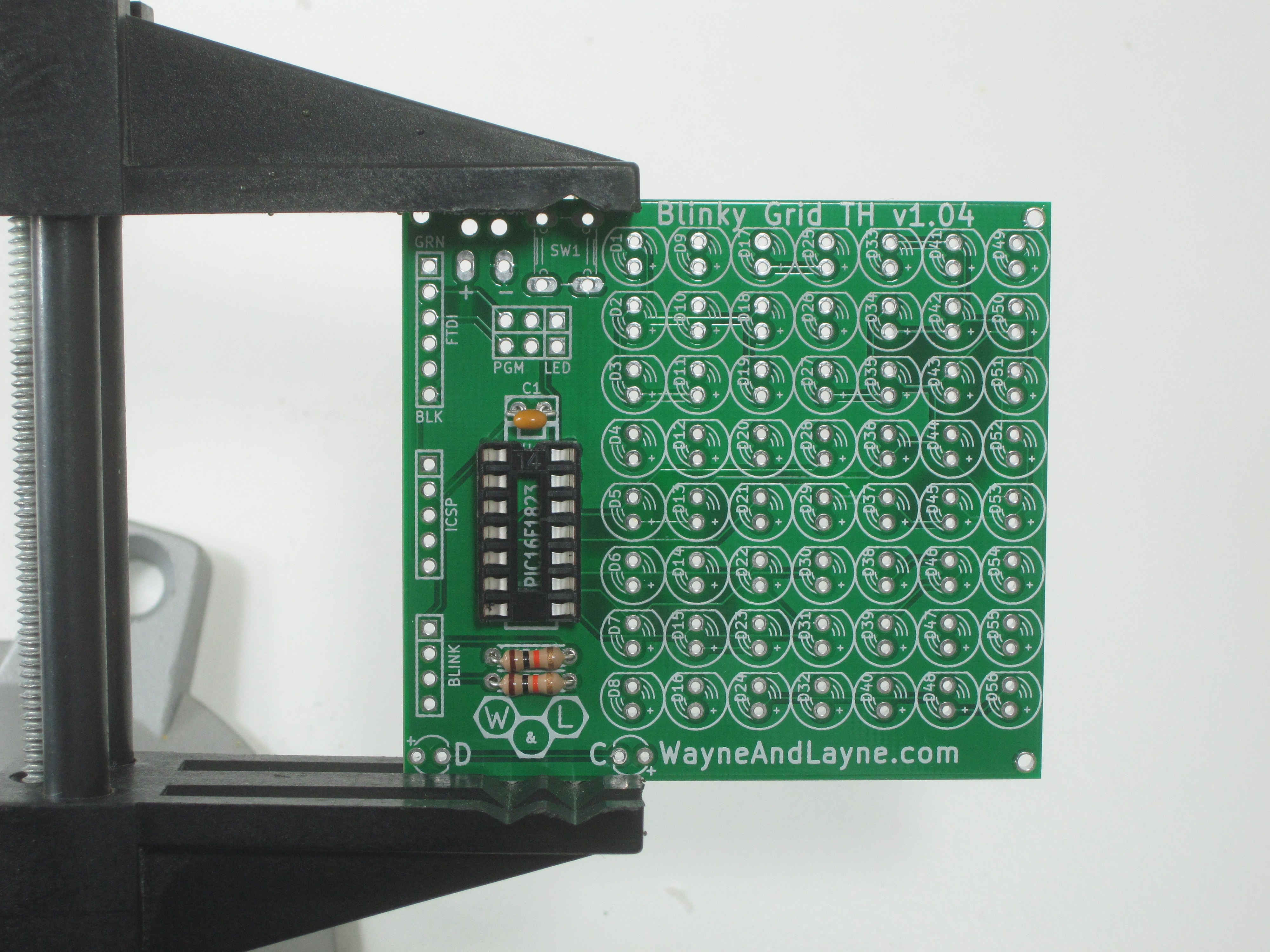
Step 4: Ceramic Capacitor
The ceramic capacitor is a non-polarized part, so it doesn’t matter which way it is inserted into the PCB. It belongs in the position labeled C1 just above the chip socket. Bend the leads on the back side to keep it from falling out. Solder and trim the leads.

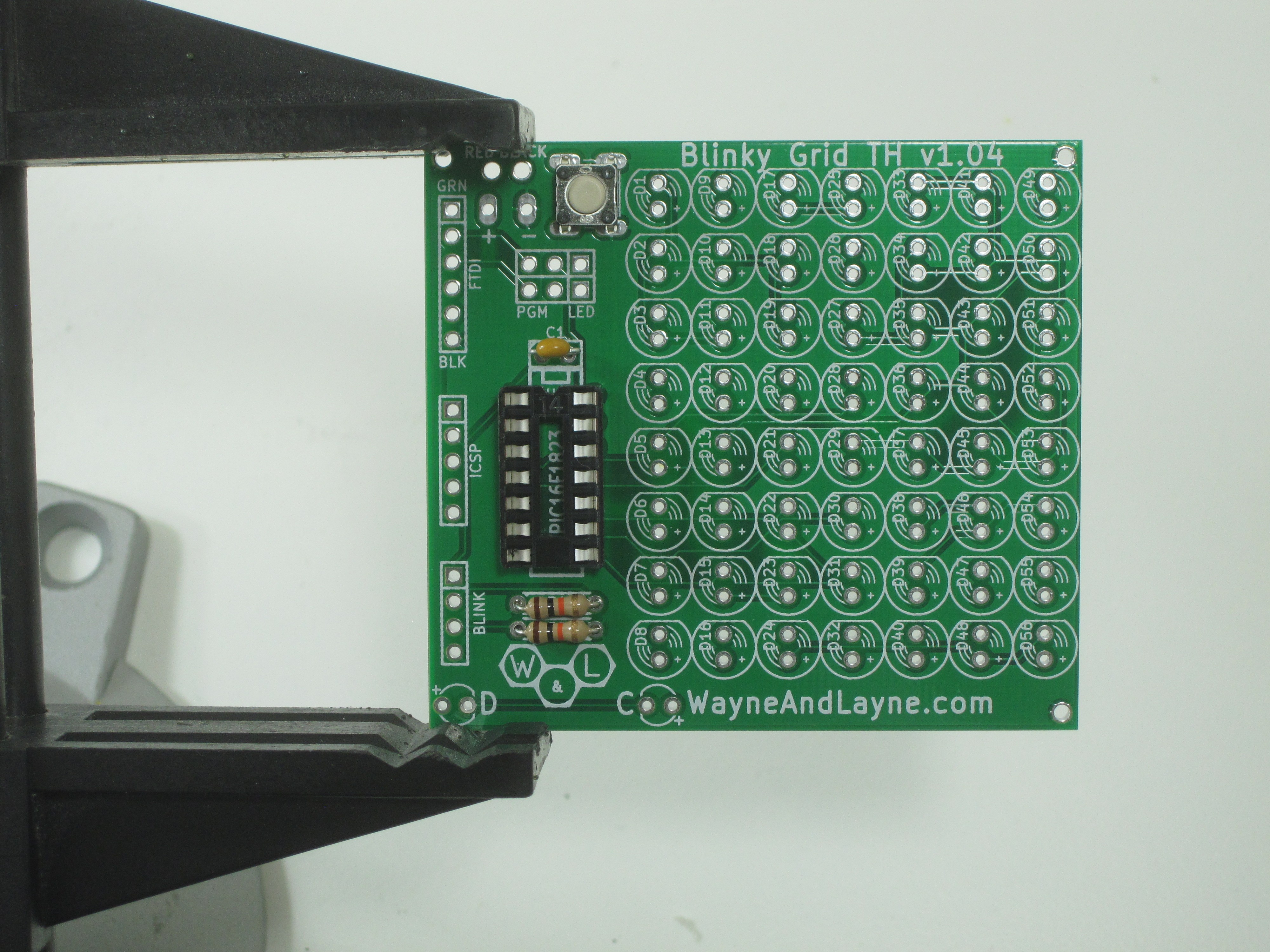
Step 5: Pushbutton
Insert the pushbutton into the holes labeled SW1. It will only fit in one alignment, so if it doesn’t fit, try rotating it by 90 degrees. You should be able to snap it right into the board without having to bend any of the leads. It shouldn’t require any bending of leads to keep it in place. Be sure to push it all the way into the board so it lays flat against the PCB.

Step 6: Light Sensors and Battery Holder
The next parts to add are the two ambient light sensors (labeled C and D on the PCB near the bottom) and the battery holder connections. You can choose to mount the PCB to the battery holder if you like, or leave them separate.
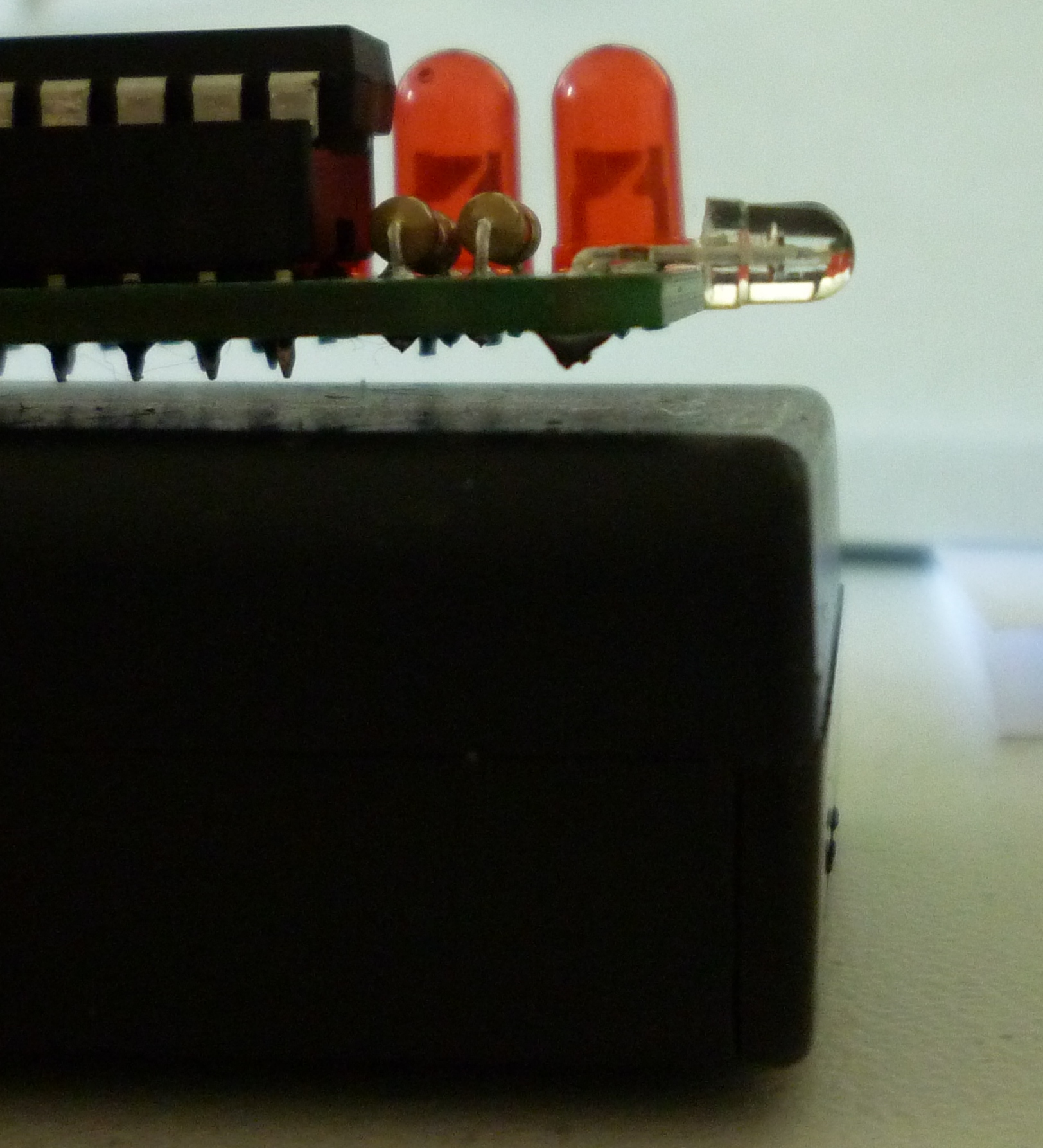
We suggest bending the leads on the light sensors 90 degrees so they face along the edge of the PCB as shown in the photo below. This arrangement will allow you to hold your Blinky kit up to your computer screen and still be able to see the first two LEDs blinking while programming. Stick the light sensors (which look like small, transparent LEDs) into the holes at the bottom of the PCB. The holes are labeled C and D, for “clock” and “data”. Just like the regular LEDs, the long lead on the sensor goes in the hole labeled with the plus sign. For each sensor, align it properly in the holes, then use a pliers to bend the sensor legs over at 90 degrees. Leave enough space between the sensor and the bend so that it can rest nicely against the PCB, as shown in the picture below. Solder them in and trim the leads. For the battery holder, stick the red and black wires through the labeled strain-relief holes near the very top of the PCB.
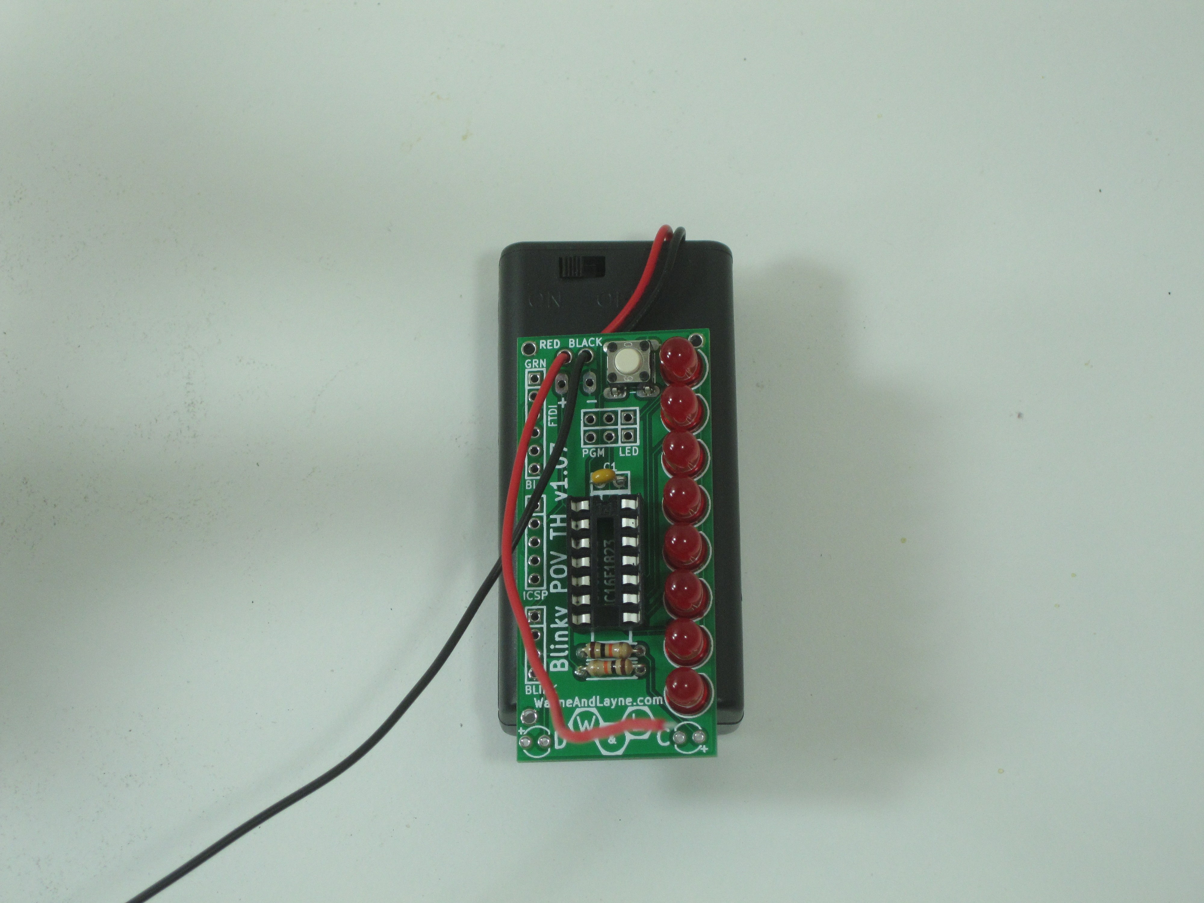
Stick the battery holder leads through from the back side, and stick the ends down through the labeled +/- holes just below the strain reliefs. Solder in the battery holder leads.

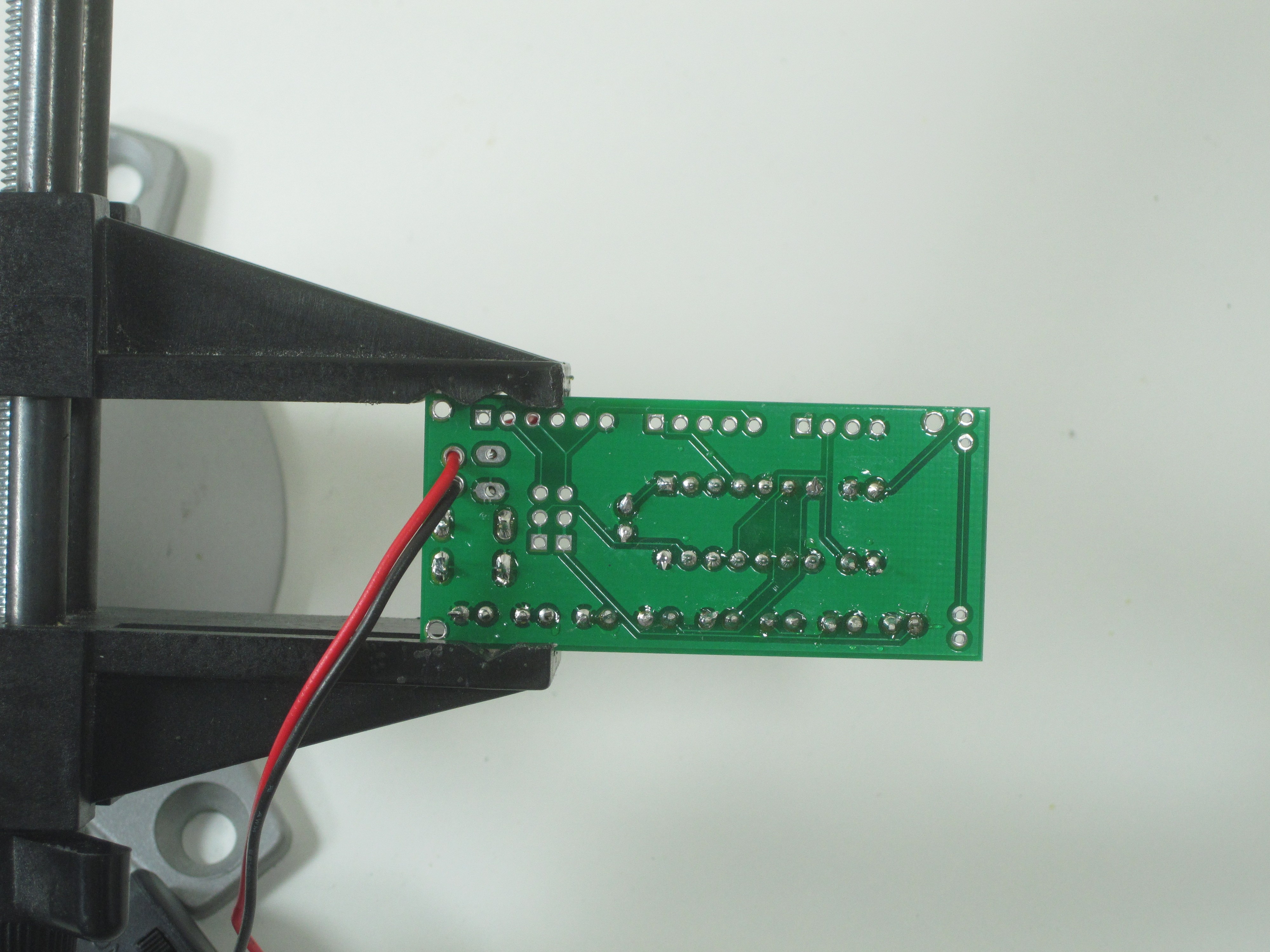
To attach the battery holder to the PCB, apply a blob of hot-melt glue to the switch-side of the battery holder. Arrange the loose wires underneath the PCB, and press it down into the hot glue. Make sure the light sensors are right next to the edge of the battery holder (so they can be pressed right against the screen), and especially make sure the switch on the battery holder is still accessible above the top of the PCB.
Step 7: Install PIC Chip
Chips in Dual-Inline Package (DIP) form usually have legs that are bent out too far to fit easily into sockets. One way to slightly (but uniformly!) bend the legs in is to press the chip against a table as shown in the photo. Insert the chip into the socket, taking care to get all the pins aligned in their holes. Make sure to put the chip in the right way! The notch lines up with the notch on the board and the notch in the socket.

Step 8: LEDs
The LEDs are the trickiest part to solder in this kit, mostly because they are polarized, and you really want them to be nicely aligned and flat against the circuit board. There are a couple ways to check the polarity of an LED. The easiest way is to look at the lengths of the two leads (wires) coming out of the LED. The longer lead is the positive lead. The positive hole of each LED is marked on the PCB with a small plus sign. Another way to tell is to look for the flat side of the LED’s base ring. This should be on the side opposite the longer lead. It should match up with the flat side drawn in the silkscreen on the PCB.
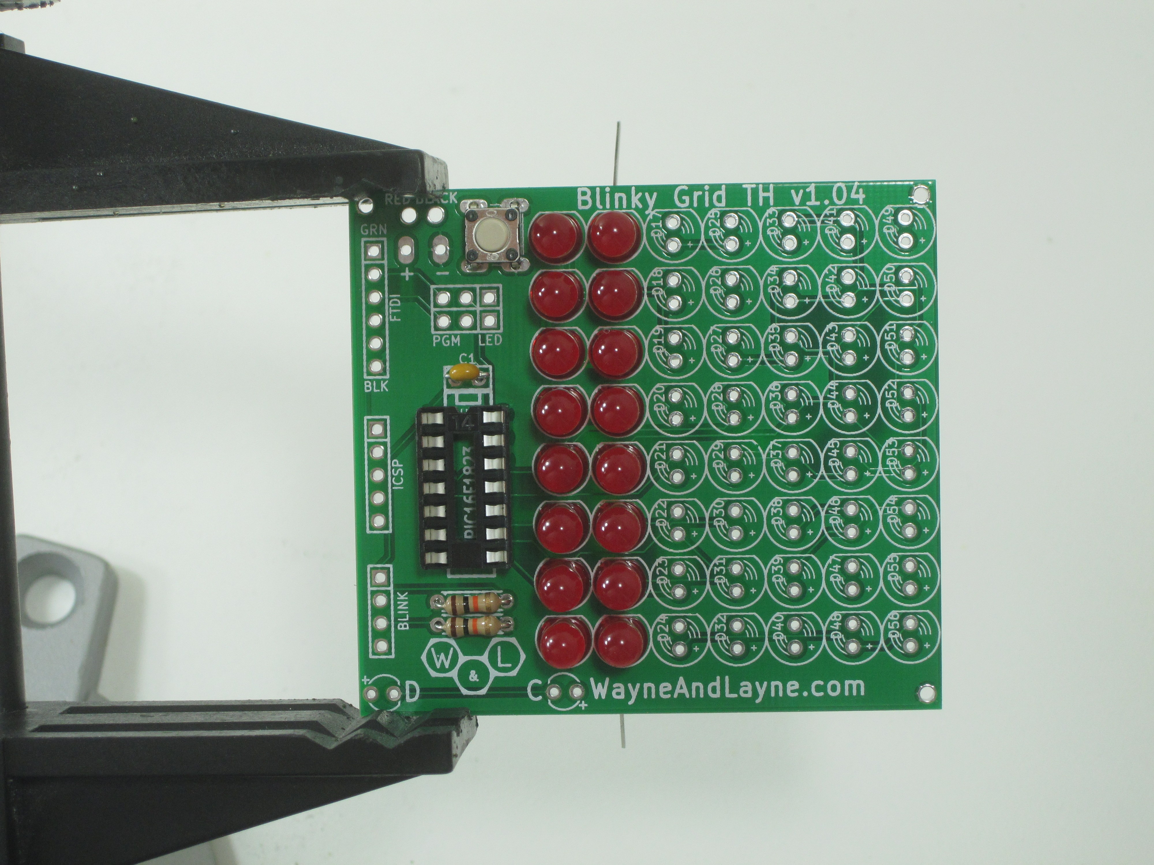
We suggest doing one column of LEDs at a time (or, for Blinky POV, all the LEDs at once). Stick eight LEDs with proper polarity through their holes in the PCB. Bend one lead on each at a 45 degree angle to keep them from falling out. Leave the other lead straight.


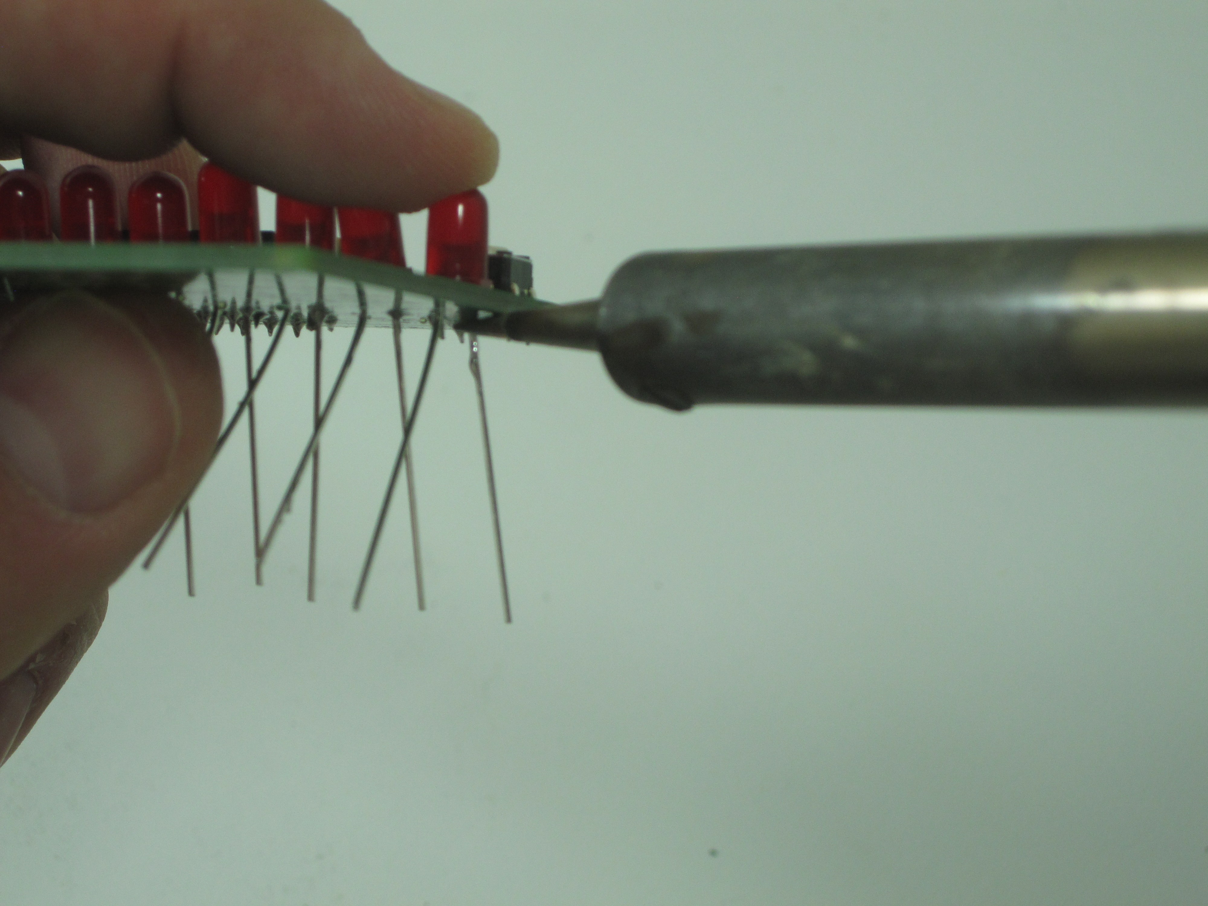
To ensure that all LEDs are flat against the PCB, you can use a simple trick for each LED. Bend one lead sideways on each LED, and then solder the straight lead only. Do this for all the LEDs in the column. Then, put a finger on one LED at a time, and gently press it towards the PCB while re-heating the one soldered lead with your soldering iron. This will allow you to ensure each LED is flat against the board and properly aligned with each other. You can then solder the other leads. Trim off all the leads when you’re finished soldering each column of LEDs.
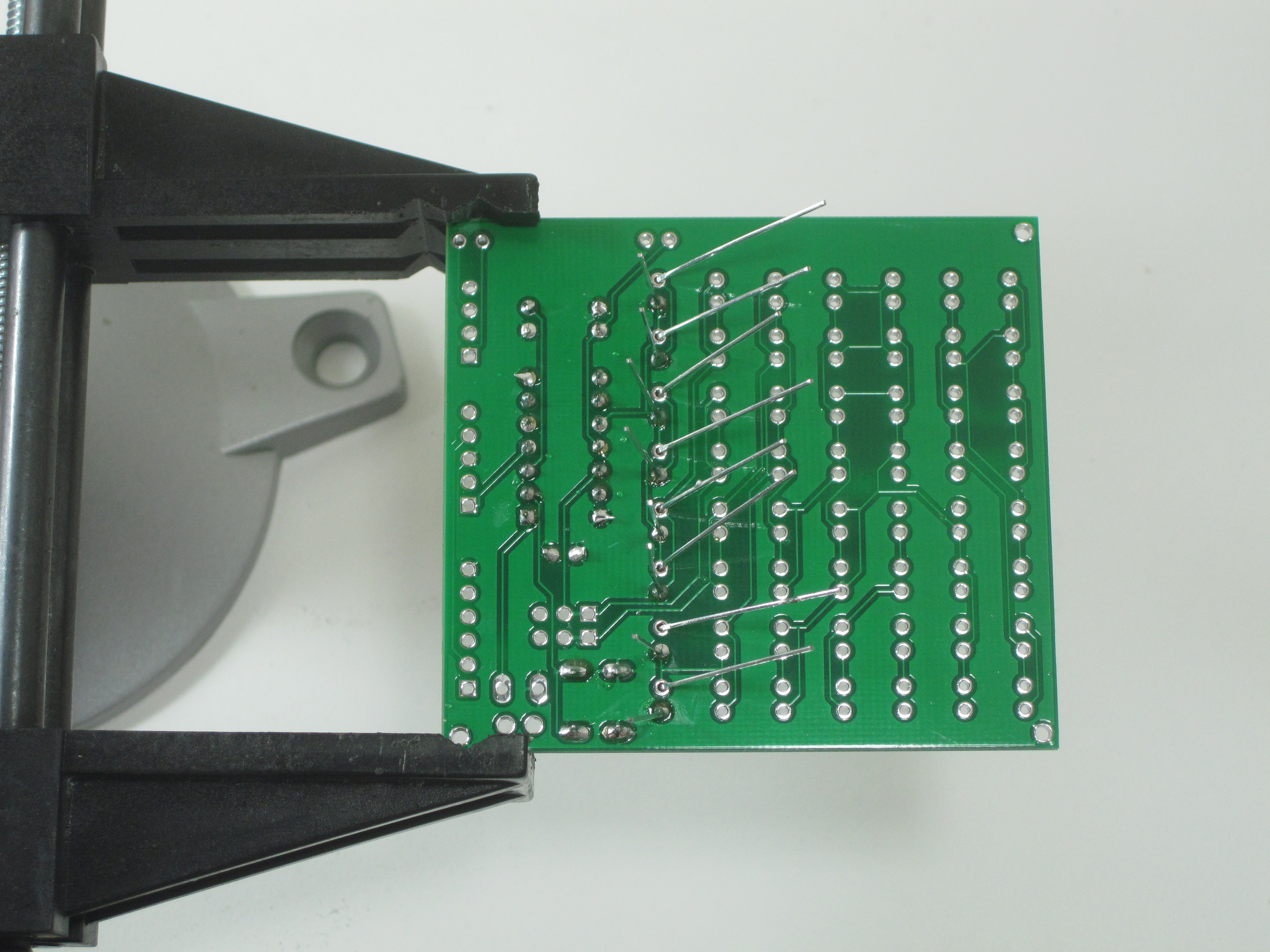
If you have a Blinky GRID, we suggest soldering one row at a time. Since it’s easier to fix (“re-work”) any mistakes before moving on to the next row, you can turn on the power after each row, and ensure that all LEDs are lighting up. Continue soldering each row in a similar way, until you’ve soldered in all 56 LEDs.
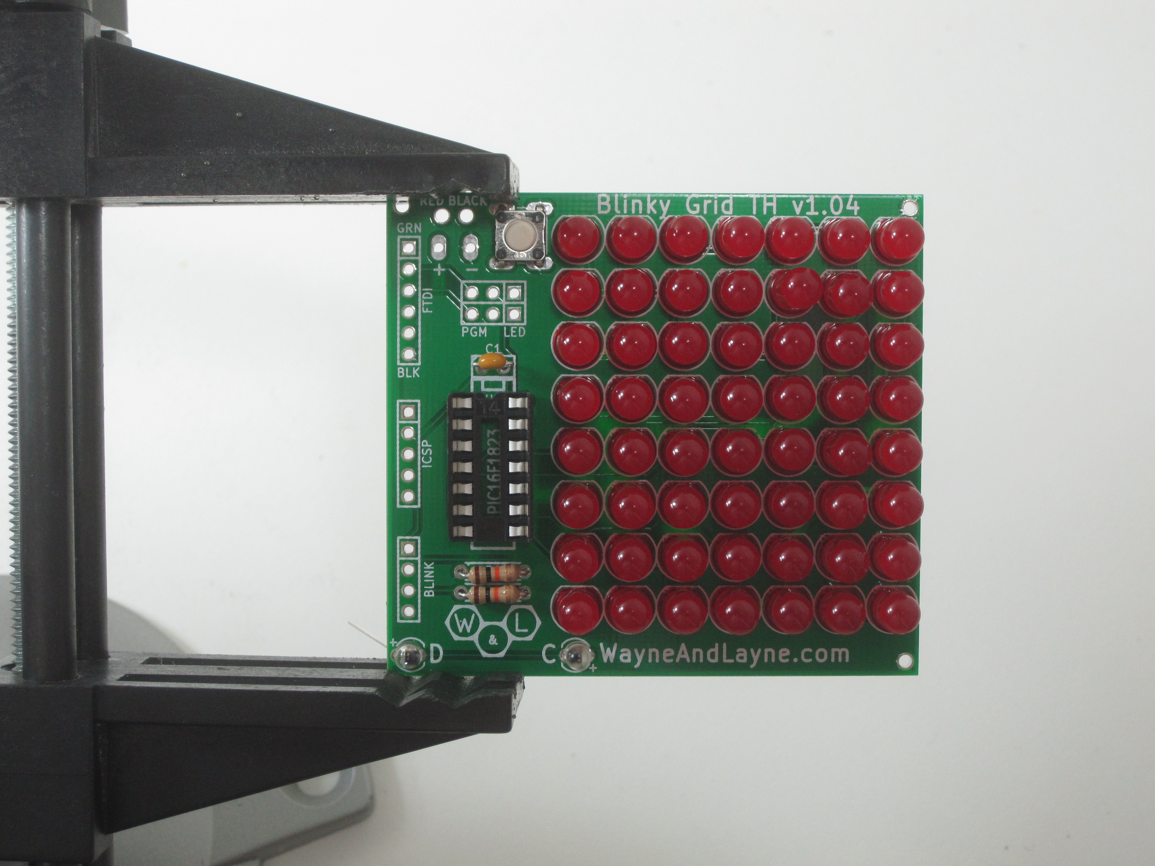
Step 9: Completion!
Give the completed board a final look over, checking for loose solder connections or shorted pads. Congratulations! You’re now the proud owner of a Blinky GRID or POV kit. Install some AA batteries and give it a try!