


Build a Blinky SMT Kit!
These instructions are for building a surface-mount Blinky kit.
The instructions for the through-hole Blinky kits are over here!
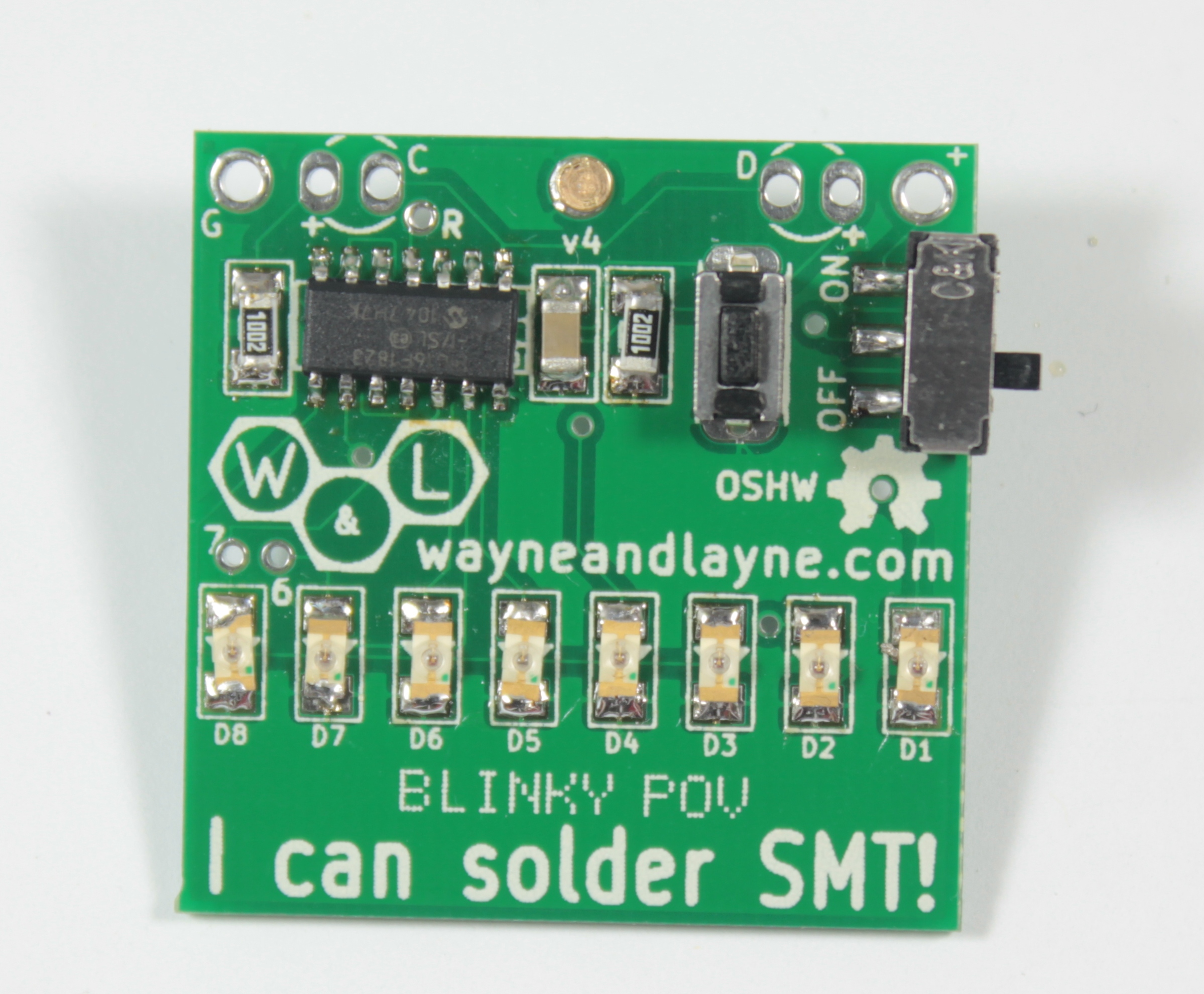
These are the building instructions for the Blinky Grid SMT and Blinky POV SMT kits. Because they are so similar, the building instructions are combined together into one document. Even though the photographs show a Blinky POV SMT circuit board, the Blinky Grid SMT circuit board is identical (aside from the number of LEDs), and all components are placed in the same positions for both Grid and POV PCBs. The LEDs shown in the photographs are red LEDs, but the same instructions apply for the blue and green LEDs as well.
Step 0: Gather Tools
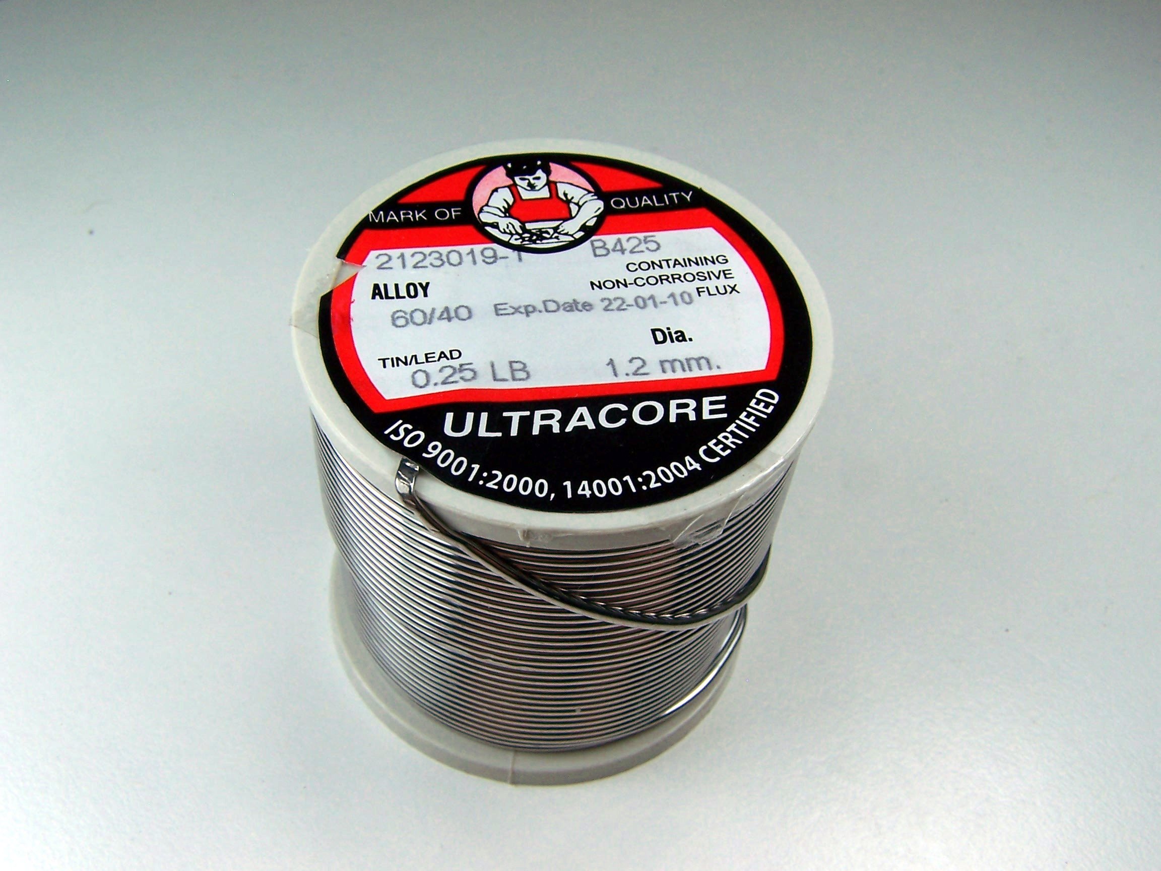
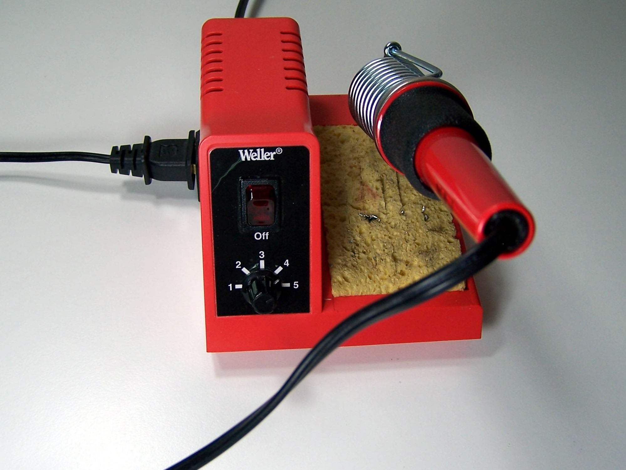
The Blinky SMT kits consist of primarily surface mount (SMT) components, but also have a couple of through-hole components. To build your kit, you will need a few common tools for soldering and electronics work. A soldering iron and solder are the most important tools. You can use any soldering iron, although a higher-quality, temperature-controlled adjustable iron will be easier to work with and give higher quality results. Any standard solder for small electronics will do just fine.
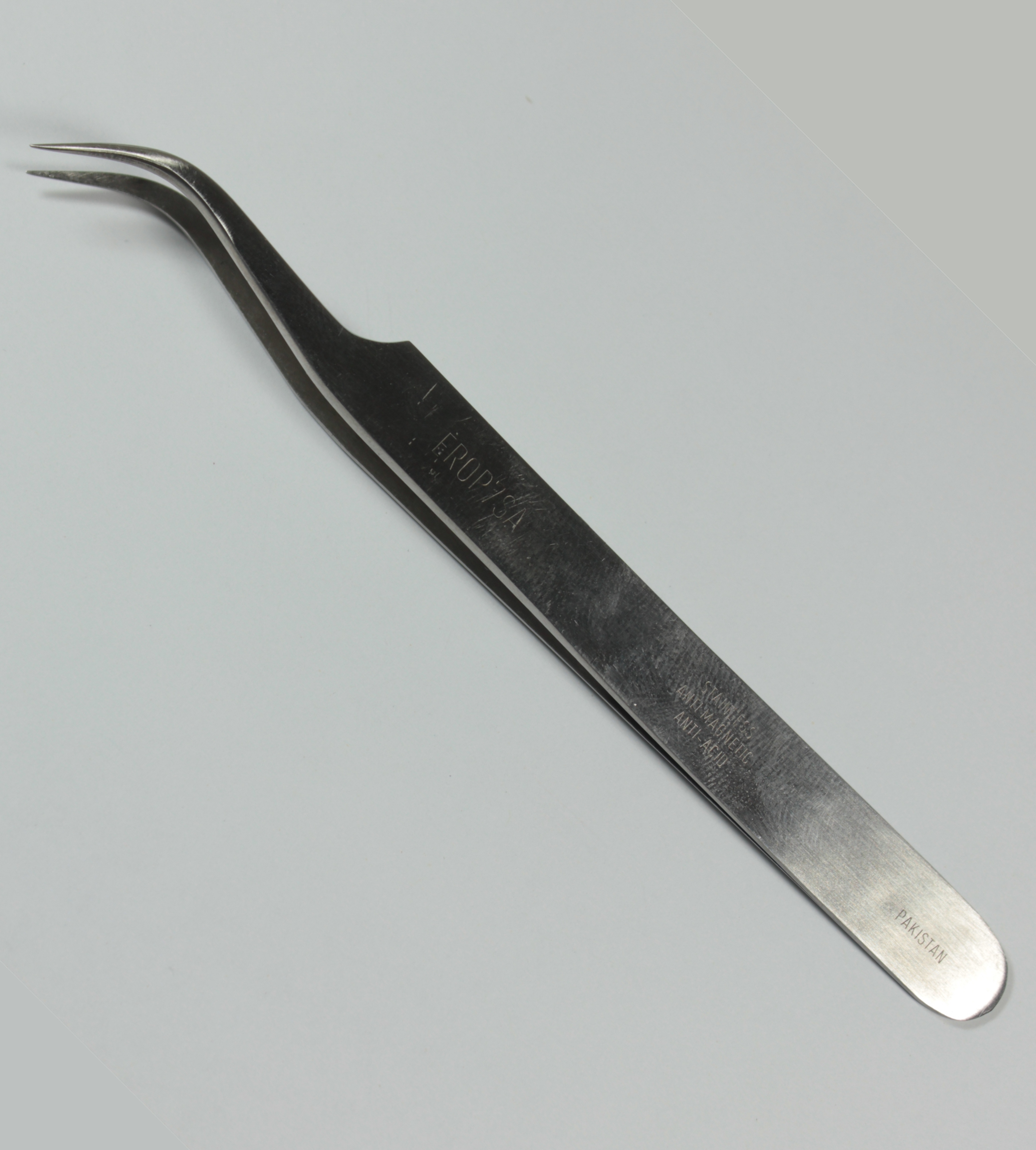
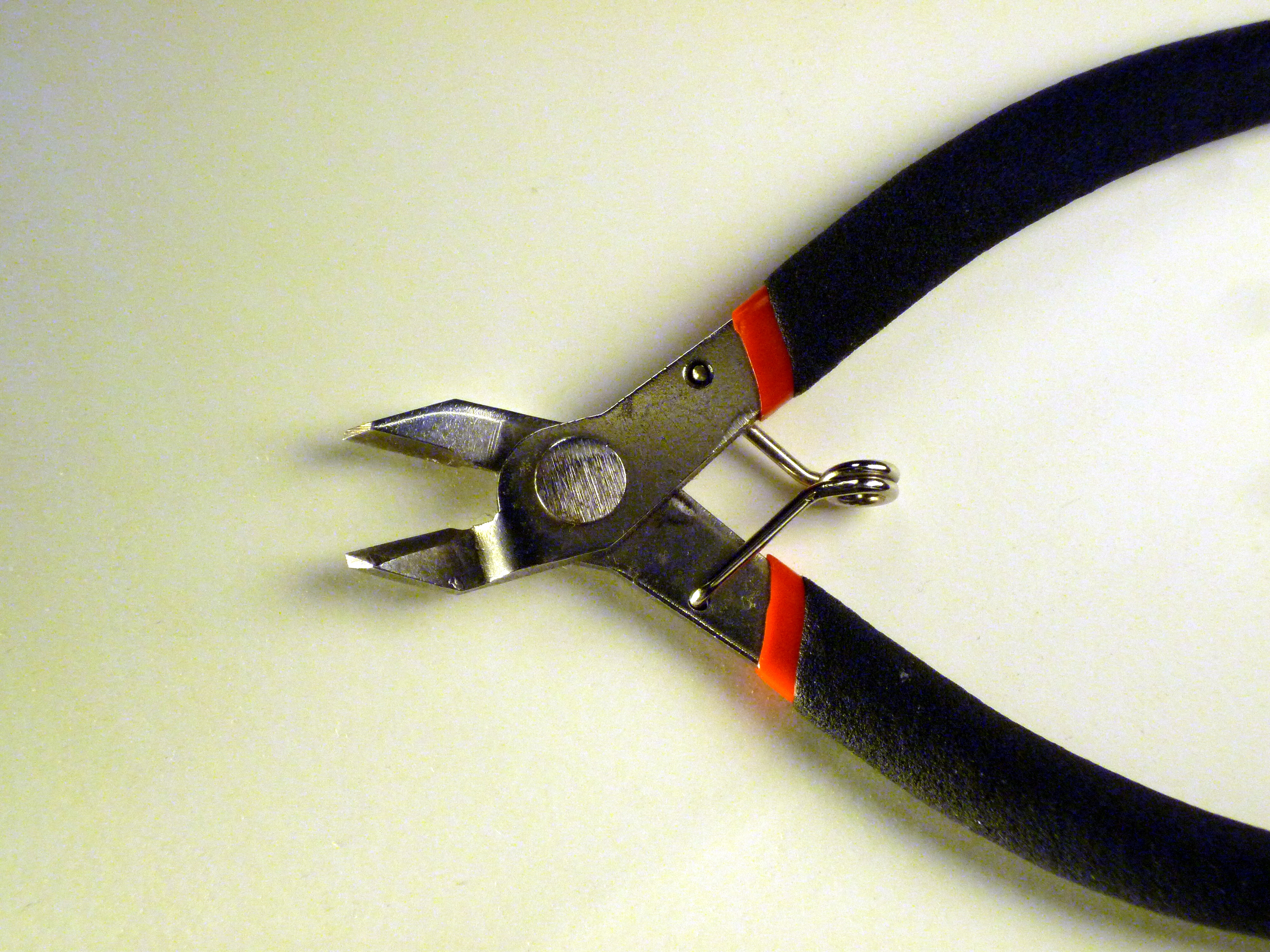
To trim the extra leads on the bottom of the pcb a diagonal pliers will work very well. A fine-tip anti-magnetic anti-static tweezers is also requred for moving and holding-down the smaller SMT components.
If you need some additional guidance and instruction on soldering, SparkFun, NASA, and Curious Inventor all have quality soldering tutorials. For surface mount (SMT) soldering, we have a few pages available, including information about hand-soldering SMT and reflow soldering.
Step 1: Part Identification
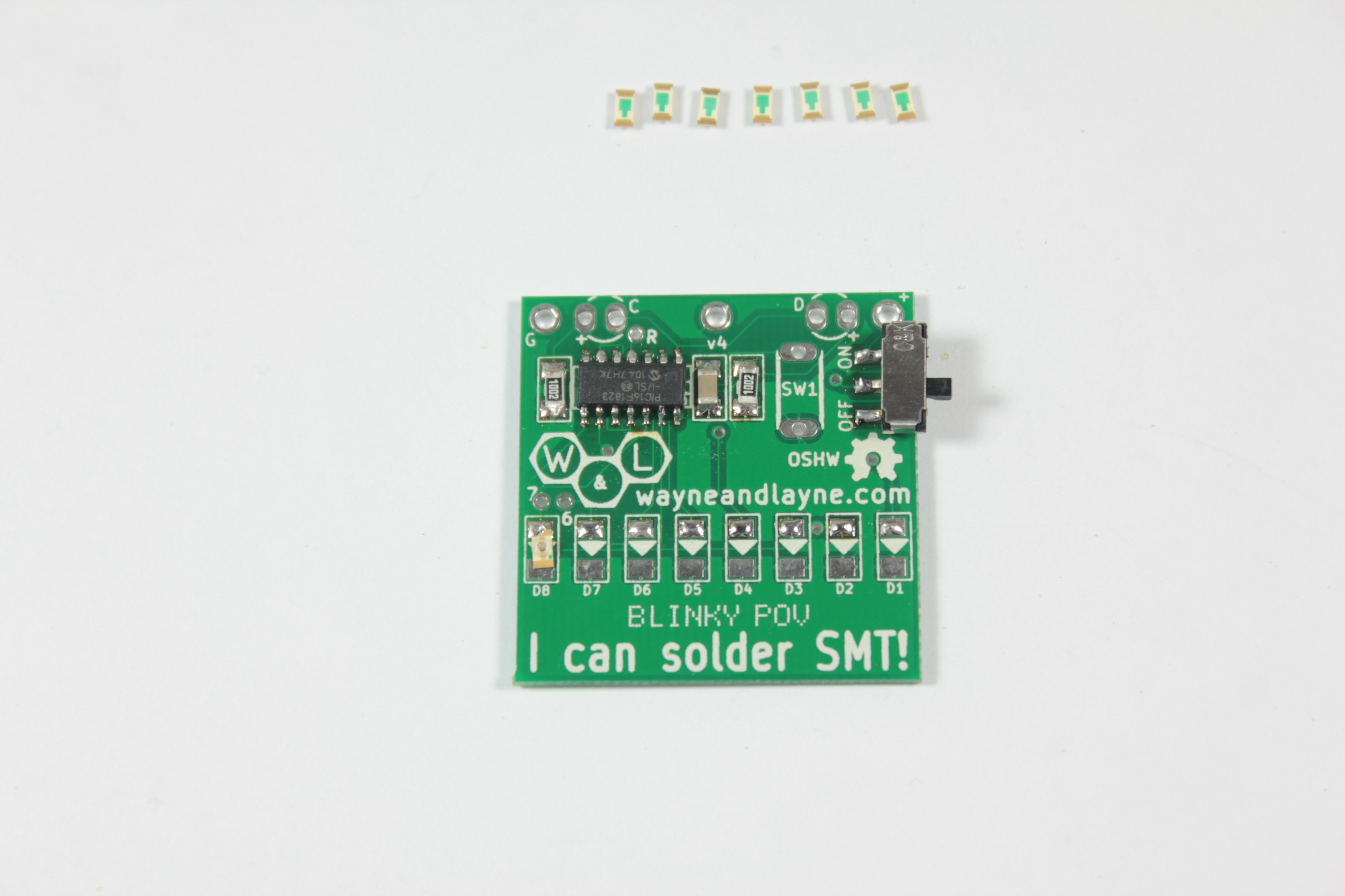
Open the bag of parts, and make sure you have all of the parts listed below. It might be easier to lay them out as shown in the picture. If you have the Blinky Grid SMT kit, you’ll have many more LEDs and a larger circuit board, but should still have all the other parts in the same quantities. Some of the parts might be taped to the instructions card in the bag. Click the photo to enlarge.

- (1) Blinky Grid/POV SMT Printed Circuit Board (PCB)
- (1) CR2032 Battery Cell Holder
- (8/56) Light Emitting Diodes (LEDs)
- (1) PIC 16F1823 Microcontroller, SOIC
- (1) Pushbutton switch
- (2) 10k resistors, 1206
- (1) 0.1 uF ceramic capacitor, 1206
- (1) Power switch, SPDT
- (2) Ambient light sensors
- (1) Butterfly clasp and pin back
This kit is easy to solder, and shouldn’t take too long. We’ll start with the surface mount parts like the LEDs, resistors, capacitor, microcontroller, and power switch. Then, we’ll solder in the through-hole parts by hand, and attach the battery holder to the back side of the PCB.
Some parts are polarized, and must be placed on the PCB a certain way, but also some parts are not polarized. In the steps to follow, if a part is polarized, we will mention which way it must be placed. The PCB is also marked to help identify the polarization.
Step 2: Choose Your Path!
On our Surface-Mount Technology page, we describe the two easiest techniques for surface-mount soldering. The first is hand-soldering where you use a regular soldering iron along with solder, wick, flux, and some good tweezers to align and hold each part in place while you solder it down. The other technique is reflow soldering, where you apply a solder paste to the PCB and place all the SMT components into the paste, and finally heat up the board which melts the solder and all the components snap into place.
Either technique is suitable for the Blinky SMT kits, and the choice is up to you. In the steps that follow, we will describe the size, shape, appearance, location on the board, and necessary alignment for each of the surface-mount parts, and show how to solder them down by hand with a soldering iron and tweezers. If you want to use the reflow technique, simply apply the solder paste and add each of the parts, then heat up the board.
Step 3: Resistors and Capacitor
The first parts to add are the two 10k resistors and the single 0.1uF ceramic capacitor. None of these parts are polarized, meaning that it doesn’t matter which end is connected to which pad on the PCB, but it’s tradition to place the parts with any writing facing upwards, so we can read the numbers to tell which part it is. As mentioned above, these steps will describe the hand-soldering technique, but the information about part identification and placement still applies to the reflow technique. The two resistors are labeled R1 and R2 on the circuit board, and have “1002” written on the resistors themselves. The capacitor is labeled C1 on the circuit board, and has nothing written on the capacitor itself.
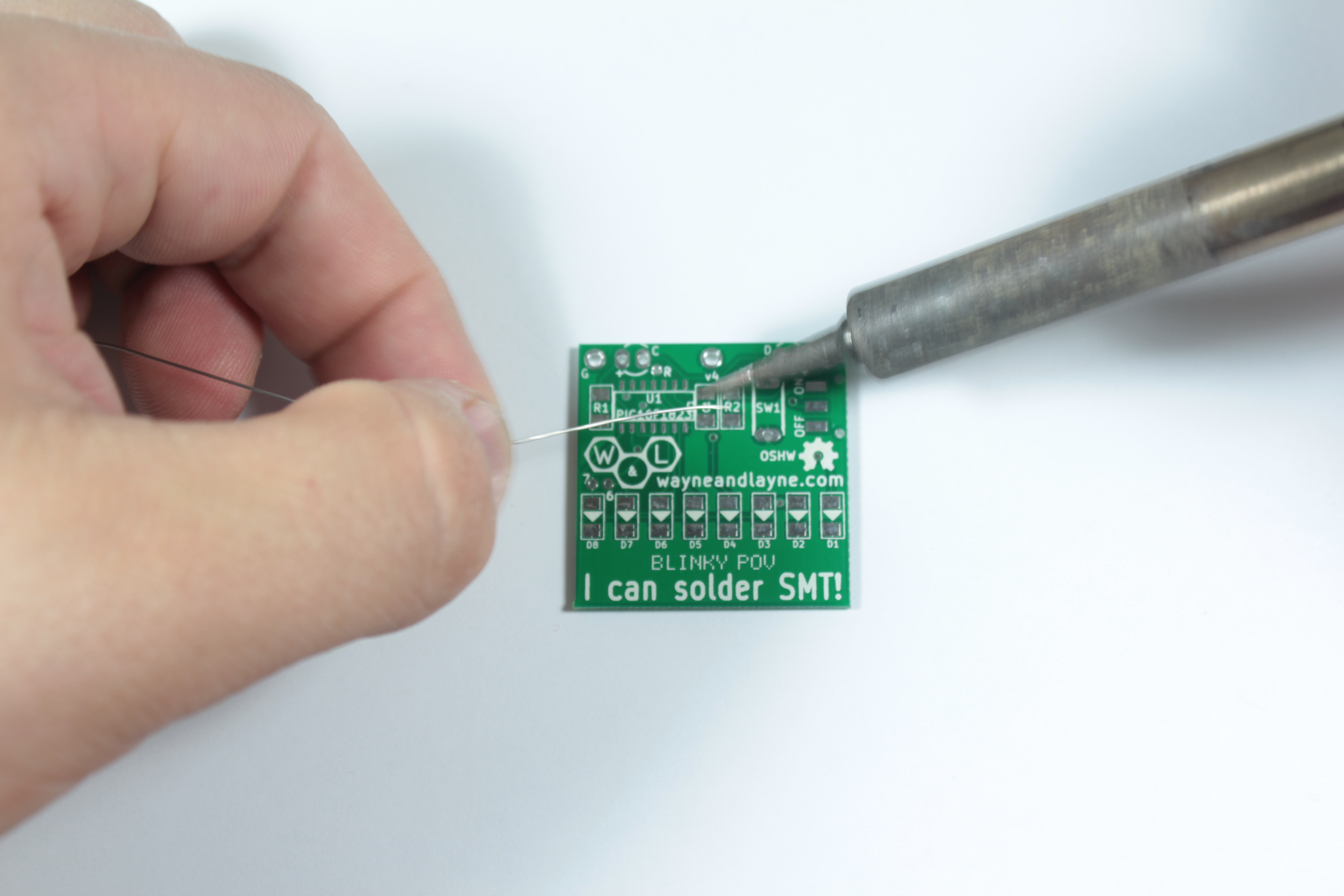
The first step in hand-soldering is to apply a small amount of solder to one of the pads by heating the pad with your iron and melting a bit of solder to the pad. If you have some thinner-diameter solder to use, that will make it easier to avoid applying way too much solder by accident. You should have a little blob of solder on the pad when you are finished.

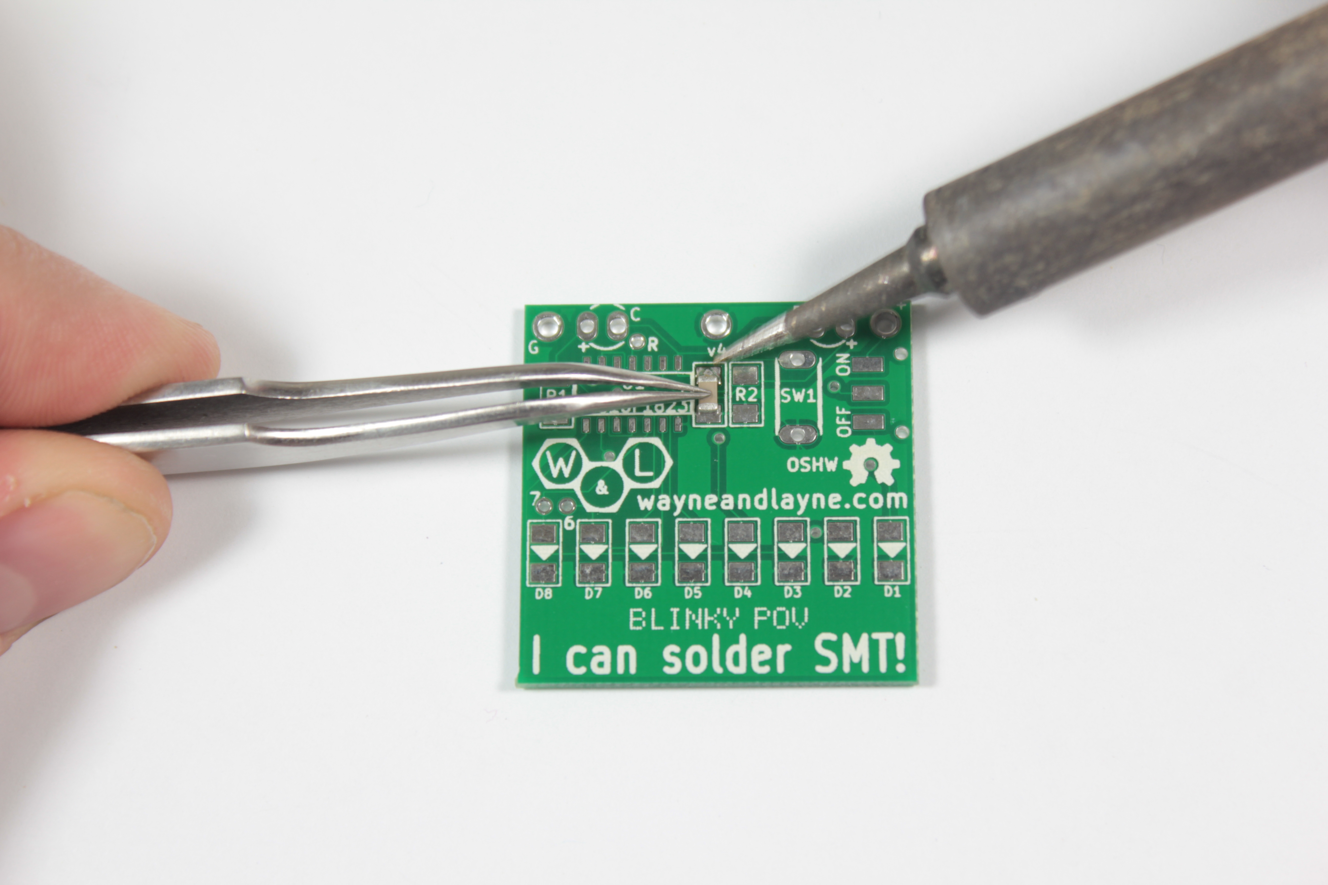
Once you have a little blob of solder on one pad of the component, use a tweezers to hold the component on the board, with one end on top of the solder blob. Touch the iron to the pin / pad with the solder. The component should be pressed firmly against the board, and both ends should be lined up with the pads. Add a little solder to the other end, creating a “fillet” between the pad and the component. Ideally, there isn’t a huge glob of solder at either the end. If there is, use solder wick to remove the extra solder.

When removing these small components from their “tape” holders, be careful that you don’t lose them! They are pretty tiny, and if you drop one in the carpet, it will be difficult to find it! We suggest working on a well-lit and empty table or counter, to minimize the chance of losing your components. We’ve also tried to include extras of some parts, just in case!
Repeat the same process for the other two components. When you’re finished, it should look like the image below.

Step 4: Microcontroller
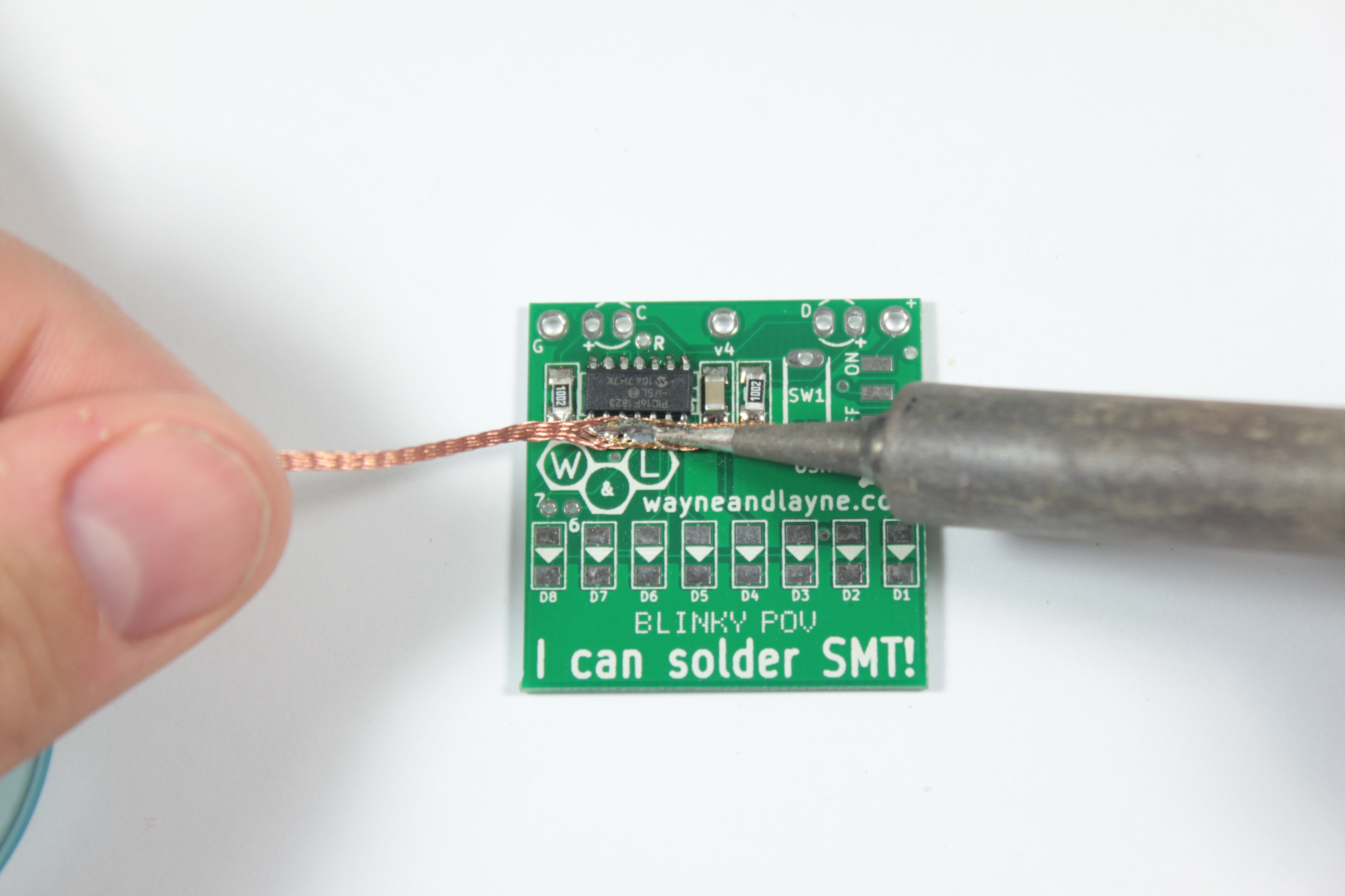
The next part to solder is the 14-pin SOIC package microcontroller. It should be taped to the instruction card in the kit bag with anti-static tape. Take the tape off the card, and use your tweezers to carefully pry the chip from the tape. SOIC stands for “small-outline integrated circuit.” Hand-soldering a multi-pin package such as this chip takes a little bit more effort than for a 2-pin package like the resistors before. To solder it down, add a little solder to one pad on the board, just like before. We suggest using a corner pin for this since they are easier to access with the tip of the iron. Use a tweezers to line up the chip with the pads on the board. Since this chip is polarized, be sure to align the dot on the chip’s surface with the notch drawn in white on the circuit board. Another way to check the polarity, is to make sure that the text on the chip looks upside-down when looking at the right-side-up circuit board (like in the second photo below). Apply a little pressure with the tweezers, pushing the chip down onto the board, into the solder, and then touch the iron to the pin on the pad with the solder to make it melt and flow around the chip’s pin. The chip should be firmly against the board, and all the pins should be aligned with their pads. You can reheat the pad a few times to get the chip pushed down all the way and the pads lined up if you need to.


Once the chip is firmly seated against the board with all pins aligned to their pads, solder another pin on the other side to tack (or “lock”) the chip in place. Solder the rest of the pins.


When you’re finished, inspect the board. Fix any solder bridges. Small bridges can be fixed easily by just heating up the associated pins and “drawing” the solder out, and larger bridges can be fixed easily with solder wick.

Step 5: Power Switch
The power switch has 3 leads and 2 plastic pegs that fit into holes on the PCB. The switch should be placed on the upper right side of the front face of the PCB, by the ON and OFF labels. Align the pegs with the holes on the top of the PCB, and push down. Solder each pin.


Step 6: LEDs
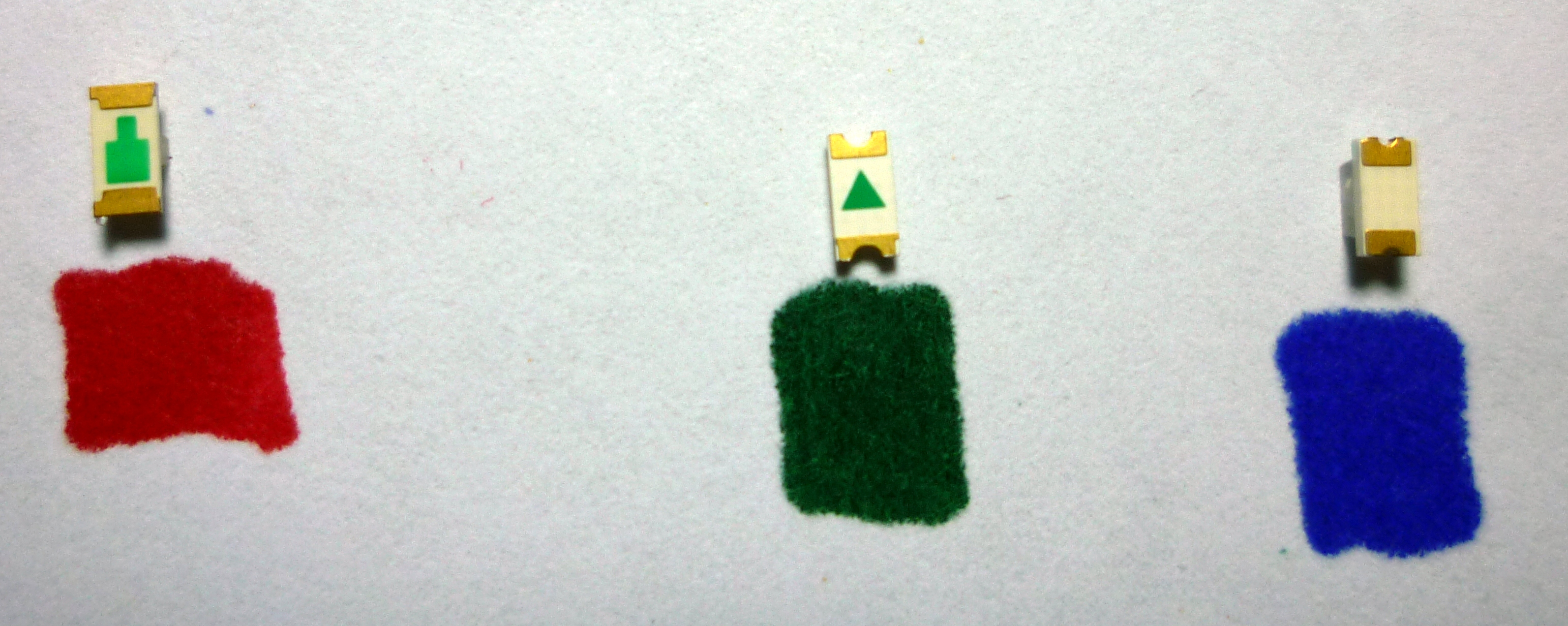
Next, the LEDs! This kit uses LEDs with a 1206 sized package. They are polarized, which means they have to go on the PCB in a certain orientation–otherwise they won’t light up! On the red and green LEDs, there are green triangles on the back of each LED, that need to be matched with the white triangles on each LED footprint on the PCB. Another way to check is that there are one or two very small green dots on the front of each LED (for the blue LEDs, the green dots are the only way to tell the polarity). The green dot on the LED should be on the narrow end of the silkscreen triangle on the board. Photographs of both the top and bottom sides of the red, green, and blue SMT LEDs are shown below to help you identify the polarity.

Be careful when taking the components out of the tape–we try to include a few extra, because we know they’re easy to lose, but working on a clean surface with lots of light can make it easier to find parts that went flying. Take your time, there are a lot of LEDs–especially on the Blinky Grid!
Once you have determined the proper alignment of the LED, you solder it down just like the resistors and capacitor from before. Tin one of the pads, then re-heat the pad while pressing the LED into place.


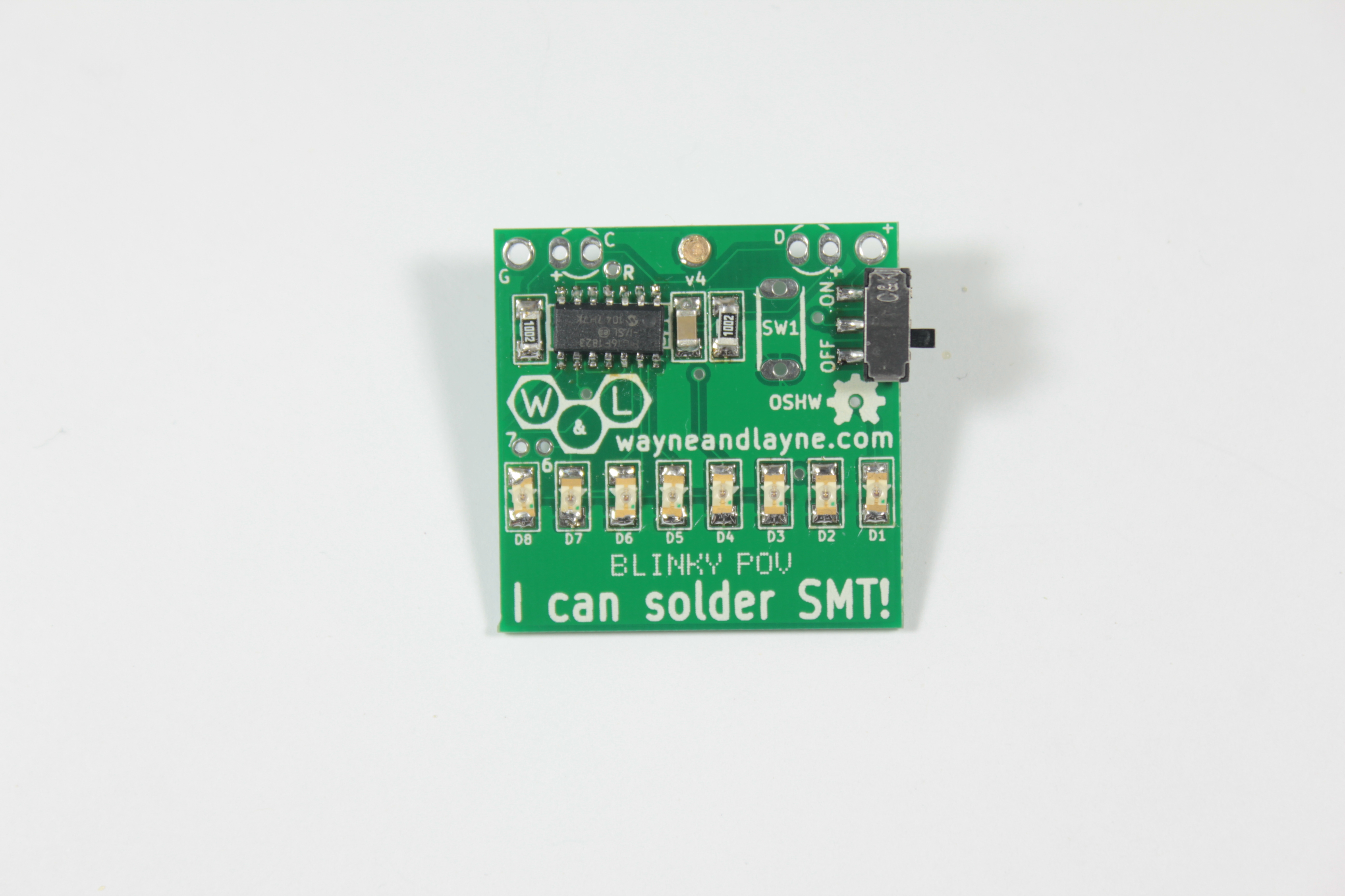
Once you have the LED flat against the board and properly aligned, solder down the other pin of the LED. Repeat for the other 7 LEDs (55, if you’re building a Blinky Grid).

Step 7: Badge pin
At this point, you’ve soldered down all of the surface-mount components except for the coin-cell battery holder, which we will do last. If you’ve been using the hand-soldering SMT technique, you’re all set for the next steps. If you’ve been simply placing solderpaste and components on your board for use with the reflow technique, now is the time to reflow your board using your reflow oven or skillet.
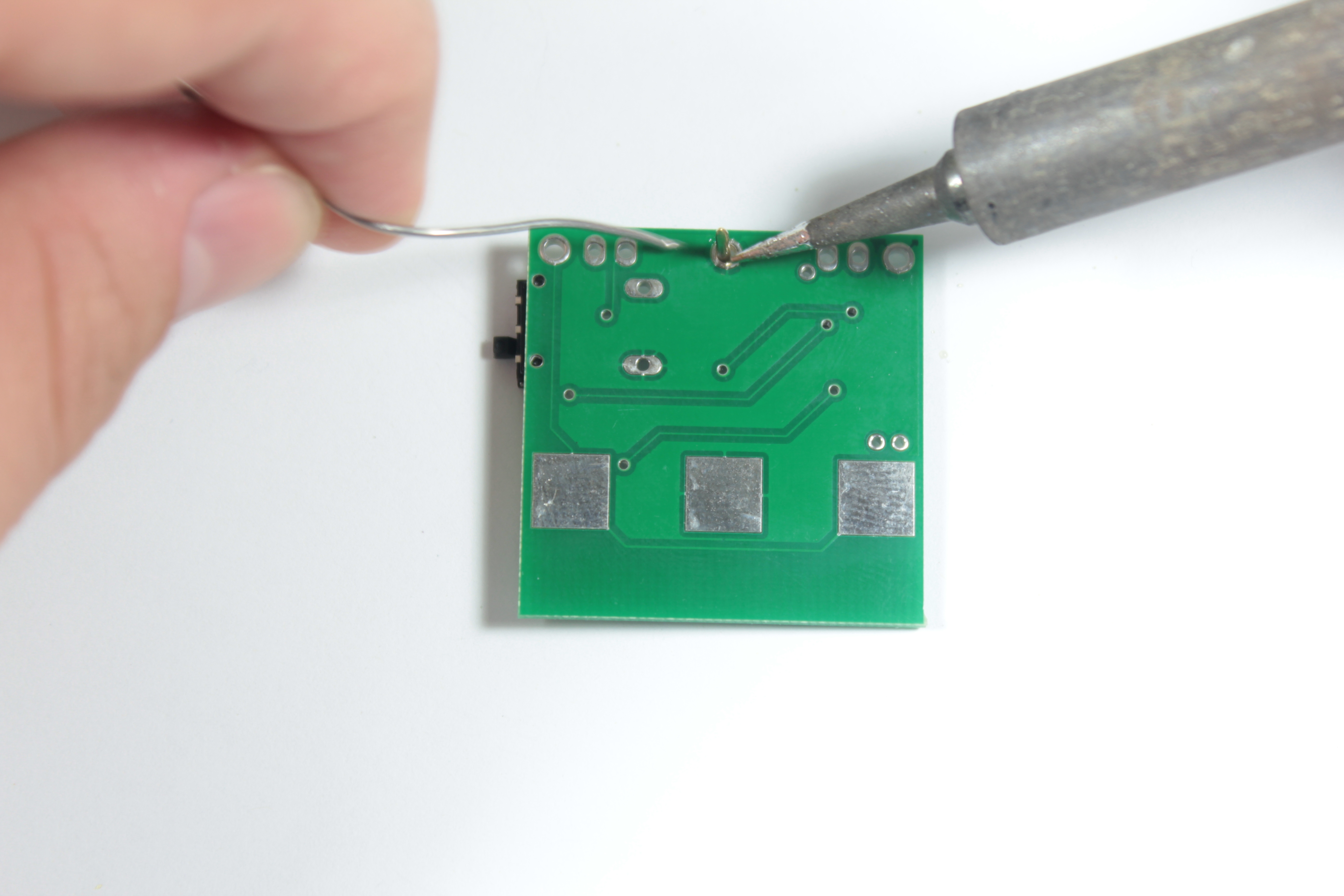
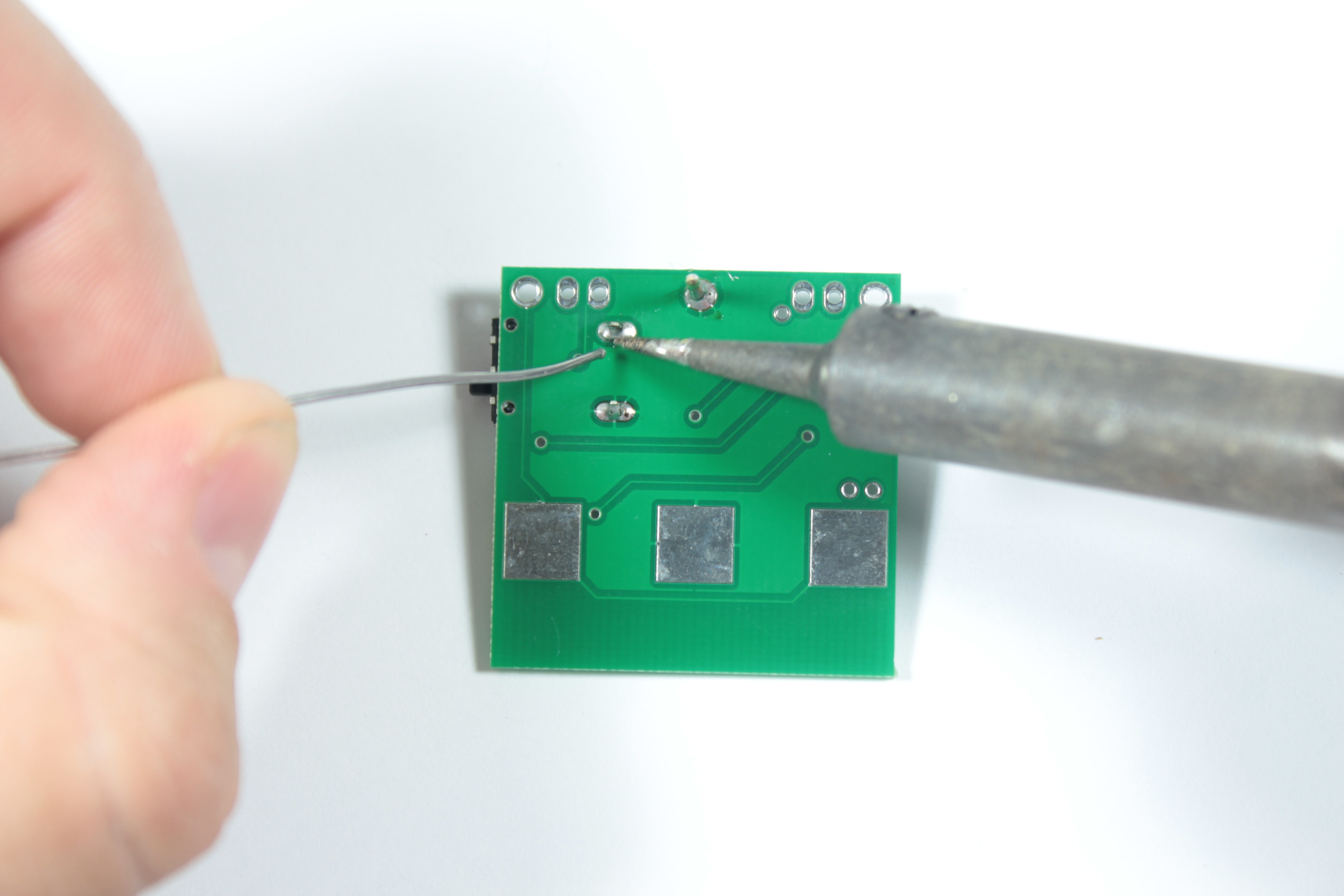
If you want to use your Blinky SMT kit as a badge, and pin it to your shirt or backpack, the kit includes a pin and back clasp for that purpose. If you want to install the pin, detach it from the back clasp and pass the pin through the top larger hole in the circuit board from the front to the back. It will probably be easier to solder the pin from the back side of the board, so flip it all over and solder the pin into place. It’s a larger component with a lot of metal, so it might take a few extra seconds for your soldering iron to heat it up, and you’ll likely need to add more solder than expected to fill the gaps around the pin.
Step 8: Pushbutton
The pusbutton is used to switch between display messages, as well as enter into the special programming mode. It is not polarized, and can go in either direction. It should snap into the board and stay put. Flip the board over and solder it in.
Step 9: Light sensors
The next components are the two light sensors that allow the blinky kit to receive data transmitted from the programming webpage.
These sensors look like small 3mm clear LEDs, and are identical but polarized. Like LEDs, the long leg goes in the hole labeled with the + sign. We like to bend the leads by 90 degrees before inserting the sensors, which makes them easier to hold up to the screen when programming the Blinky kit. Flip the board over and solder both leads of the two sensors. Trim the leads with a diagonal pliers so they are flush against the board.


Step 10: Battery holder
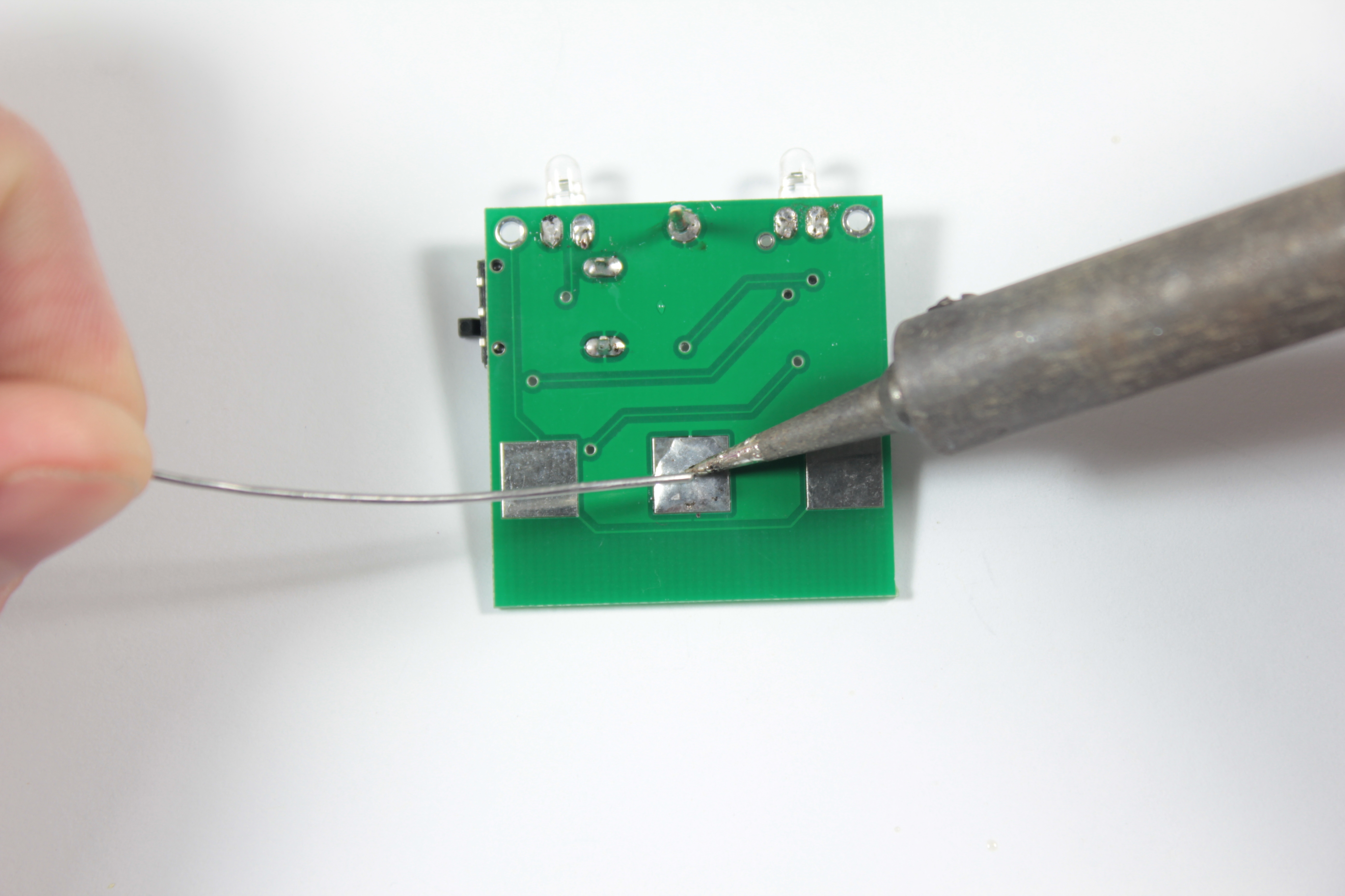
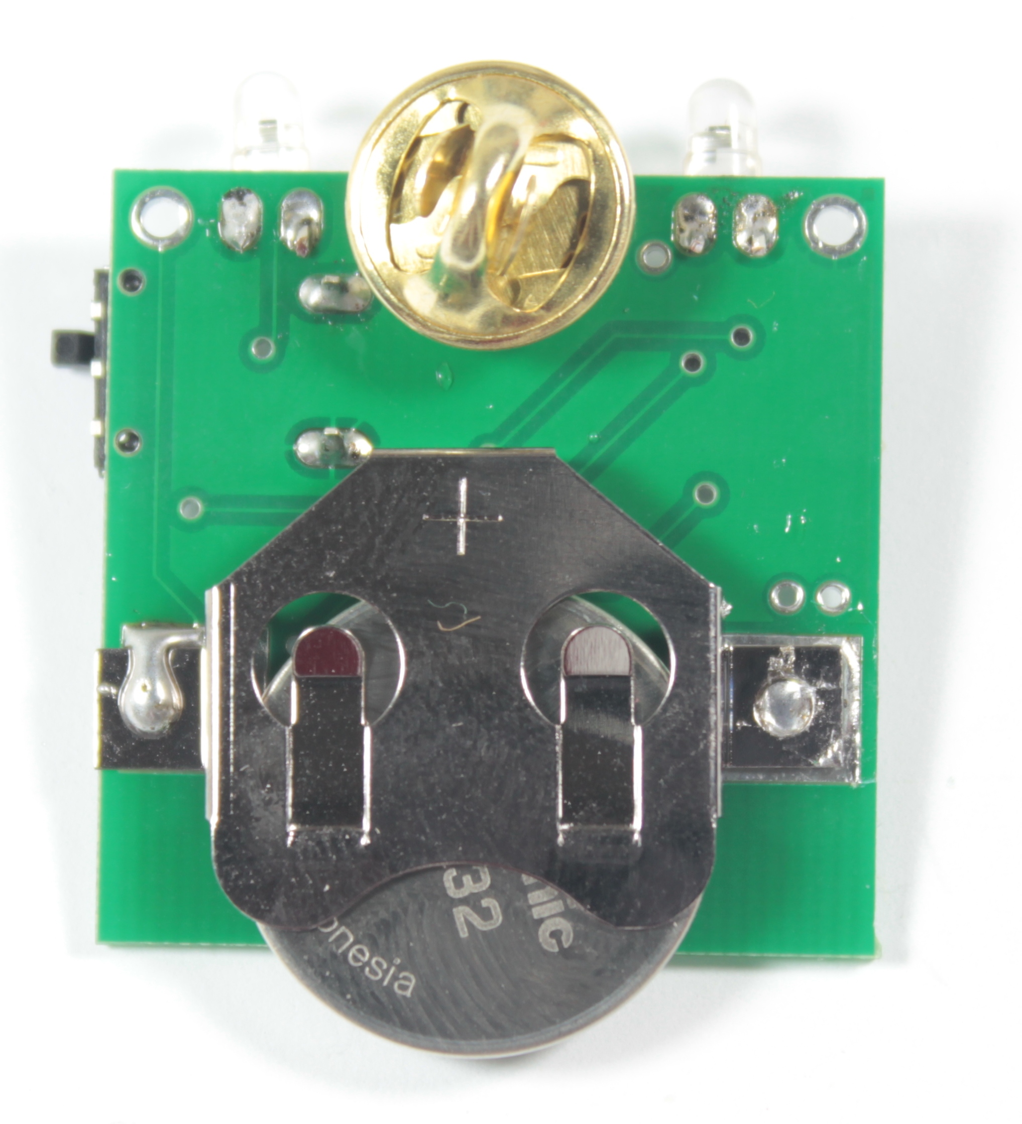
The CR2032 battery holder has two leads that extend outwards on the left and right side, which are soldered down on the back side of the circuit board. We suggest having the opening of the battery holder face down, otherwise the badge pin will interfere with inserting the battery cell. To help the battery stay in place better, you should add some solder to the middle pad. Not too much, but enough to form a tiny little pillow of solder across the whole pad. Then, place the battery holder on the board, and use your soldering iron and solder to tack down one of the leads, making sure that the other lead is still aligned with the other pad.

Step 11: Check your work
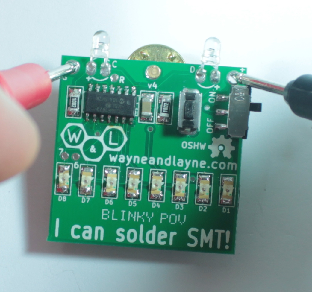
Now is a great time to look over your board and check for any shorts or bad solder connections. If you have a multimeter, you can measure the resistance between the two holes in the upper corners. These holes are connected to the battery terminals, and the meter should measure a very large resistance between the two holes. This means that there are no shorts in your power supply wires (which would be a bad thing to have happen!)
Slide a CR2032 battery into the battery holder, with the + sign facing upwards. Slide the power switch from “off” to “on”, turn the board over, and you should see the LEDs lighting up!
Step 12: Completion!
Give the completed board a final look over, checking for loose solder connections or shorted pads. Congratulations! You’re now the proud owner of a Blinky GRID or POV SMT kit, showing the world that you now know how to solder surface-mount technology! Why don’t you give it a try!
