


Kicad Tutorial: Gerber file generation
This is part of a series of short tutorials on advanced topics of using Kicad, the favorite schematic/PCB design software here at Wayne and Layne.
Once you’ve finished working on your PCB and are ready to send it off for fabrication, one step remains: “Plotting” the PCB design to Gerber files. The Gerber file format is a very old format with its roots in the 1960s, and is used to completely describe a single layer of a PCB design. You need to generate one gerber file per layer of your PCB design (Copper, SolderMask, and SilkScreen, for both the top and bottom sides, plus the PCB Edges layer). The information about where the holes are drilled, and what size the hole should be, are stored in a separate file with a different format, called the Excellon format, named after the market leader in CNC drilling machines during the 1980s.
To generate the gerber and drill files for production, click on the Plot toolbar button in PCBNEW. It is located in the top toolbar and looks like a printer with a “P” overlaid. This brings up the plot dialog box. (Click to enlarge image.)
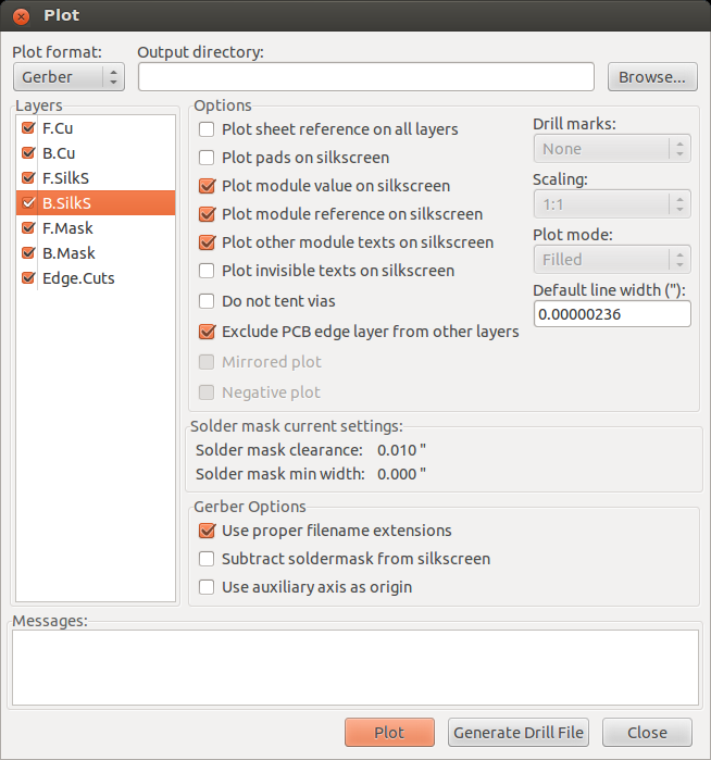
Here, ensure that the “Plot format” is “Gerber”. Leave the “Output directory” field blank, and it will default to saving the files into the project directory. Make sure you check all the layers you want to send to production. If you didn’t use back-side silkscreen, or don’t want to use any back-side silkscreen (some places charge extra for that), you can un-check the B.SilkS layer. The other checkmark boxes are the defaults, but ensure that “Exclude PCB edge layer from other layers” and “Use proper filename extensions” are checked. Press “Plot” to generate the files, one per layer. You will see output in the “Messages:” box at the bottom. When that is finished, click “Generate Drill File” to bring up the next dialog box. (Click to enlarge image.)
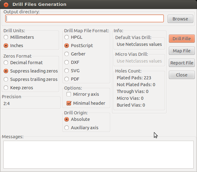
Again, leave the “Output directory” text field empty. The settings here are very important, especially the Drill Units (Inches), Zeros Format (Suppress leading zeros), and Options (Minimal header). You absolutely must check “Minimal header” and un-check “Mirror Y-Axis”. Since we aren’t making a drill map, the “Drill Map File Format” option doesn’t matter. Click the “Drill File” button to generate the drill file. Then press “Close” and “Close”.
Now you can zip up the generated gerber/drill files and send them off for fabrication. At Wayne and Layne, we really like the prototype PCB fabrication services from OSH Park. They describe themselves as
This is a community printed circuit board (PCB) order. We take designs from lots of people, put them all together on a panel and then order the panel from a fab. Since we’re all splitting the panel setup cost, this lets us make circuit boards inexpensively.
This service grew out of the DorkbotPDX PCB Order run by @laen and now comprises of a two-layer panel every other day, a four-layer panel every three weeks and a periodic two-layer medium run service for people needing more than 150 square inches of board.
They have very inexpensive rates, decent production time, and very high-quality output. Plus, the gold and purple boards just look very nice! Here are the details about pricing and design rules (minimum clearance and trace width, minimum hole size, etc).
Other tutorials in this series:
Great tutorials!
I have question – is there any possibilities to make in KiCAD a teardrops on pads?
Something like these: http://dangerousprototypes.com/forum/download/file.php?id=6979&t=1
Many versions of Kicad had “Mirror Y Axis” enabled by default for the drills file. That needs to be disabled too.
Jan, I don’t know about teardrop shapes like that, but you should be able to make something close by combining different sizes of traces and oval pads. You can make pads at any angle and offset, so you can do cool things like these pads:
Laen, I have no idea why it defaults to Mirror Y Axis being set, but I added another sentence to the post to emphasize that that option needs to be unchecked. Thanks for the heads-up!
Thanks for the instructions.
One issue I’m running into: when I create a board the NPTH (non plated through holes), kicad generates 2 drill files (“boardname-NPTH.drl” and “boardname.drl”), which it doesn’t look like OSH Park expects (the renders aren’t quite right). Is there some toggle I haven’t located that needs checking? Or will it work despite the mis-rendering?
Cody, I’ve seen the same thing, but I’m not sure how to fix it. I don’t know much about using both plated and non-plated holes in the same PCB design. Do you know if other tools produce a single drill file for both types of holes?
I also got caught by the *NPTH.drl and *.drl issue in my OSHPark order. Support replied that their system only expects one .drl file and omits the second. He recommended merging the two files with gerbview or gerbv before submission if I can’t force Kicad to do this. They ‘re working on better detection of drill issues as they are a common problem.
I got caught with the NPTH and PTH drill file issue too and received a set of boards from OSHPark with only the NPTH holes drilled 🙁
Using GerbV, I merged the two drill files generated from KiCad and that seems to work.
Thanks for the concise tutorial on this; it saved me from an expensive mistake with my first Kicad-designed board. I very nearly ordered boards with only NPTH drill hits.
Thanks for sharing. I had some issues in my gerber files with OSH Park.
Excellent Article. Appreciate it!
Great article, thanks!
Just to note– as of February 2016, Kicad has an option in the drill file export dialogue to merge NPTH and PTH files into one
Why have you selected Postscript as the Drill Map File Format instead of Gerber in the included image?
Michael Mast: The Drill Map File is a separate file from the required drill file. Since we don’t use the Drill Map File this setting doesn’t matter. Also, since this was from the older kicad version, these settings have likely changed in the latest stable releases.
Hi,
Is it possible to export drill files in *.txt format also?
Br,
Danijel
Hi Danijel, the drill file is a plaintext file, but has a different filename extension (.drl instead of .txt). You can open the file in notepad or any other text editor to see the contents. Should be plain ASCII characters in the file, if I remember correctly. Good luck!