


Design
Parts of the Bricktronics Shield (and Arduino)

Sensor Ports (A, B, C, D)
The Sensor Ports connect NXT sensors to the Arduino. Because many sensors are wired differently, not all sensors work in all ports. More details are available on the Bricktronics Sensors page.
Motor Ports (E, F)
Each Motor Port can drive an NXT Motor and monitor its position using the built-in encoders.
Motor Headers (The leftmost black strips with yellow pins, in front of each motor port)
Each Motor Port has a Motor Header for driving other motors. The top pin is tied to VIN on the Arduino, the middle two are the motor driving outputs from the L293D, and the bottom pin is ground.
Most people probably won’t use these, but we’ve provided it for maximum flexibility.
Do not put jumpers on these pins.
USB Port (G)
This is how the Arduino gets reprogrammed, and if you’re not using the Ultrasonic sensor or any motors, the Arduino can get power from the USB port as well.
DC Jack (H)
This jack accepts a 5.5mm/2.1mm jack. It needs to be center positive, and for this shield, you want the output voltage of the supply to be between 7.2 V and 9 V, in order to power the motors and sensors safely. If you’re not using motors or the ultrasonic sensor, you can skip this, and just power from the USB port.
Transistor Driver Headers (The “middlemost” black strips with yellow pins)
You don’t need these to drive NXT motors or sensors, but we found them necessary for a project in Make: Lego and Arduino Projects, so we included them on the shield for everyone. They’re used to control voltages greater than 5V, like 12V LED modules.
The Bricktronics Shield comes with two TIP120 Darlington transistors. They’re set up with current-limiting base resistors. The connections are brought out to the EXT1 and EXT2 headers. Two diodes are included. These are for protecting the Bricktronics Shield when you use the TIP120 to drive an inductive load like a motor.
For more information on how to use these, see the great bildr page, High Power Control, Arduino + TIP120.
The Bricktronics Shield v1.03 has two diodes silkscreened on the PCB. These aren’t really useful–the TIP120 already had a diode that does that internally. It won’t damage anything if you connect a diode to these by mistake. We’ve included two extra diodes in case you didn’t look at the instructions during assembly, and solder in your protection diodes. On v1.04 and newer of the Bricktronics Shield, the diode connections are fixed so they will help protect the TIP120 from “Back EMF” if you connect a motor or solenoid. For more details on how the diodes are connected on the Bricktronics Shield, please refer to the schematic diagram for v1.03, v1.04, and v1.05.
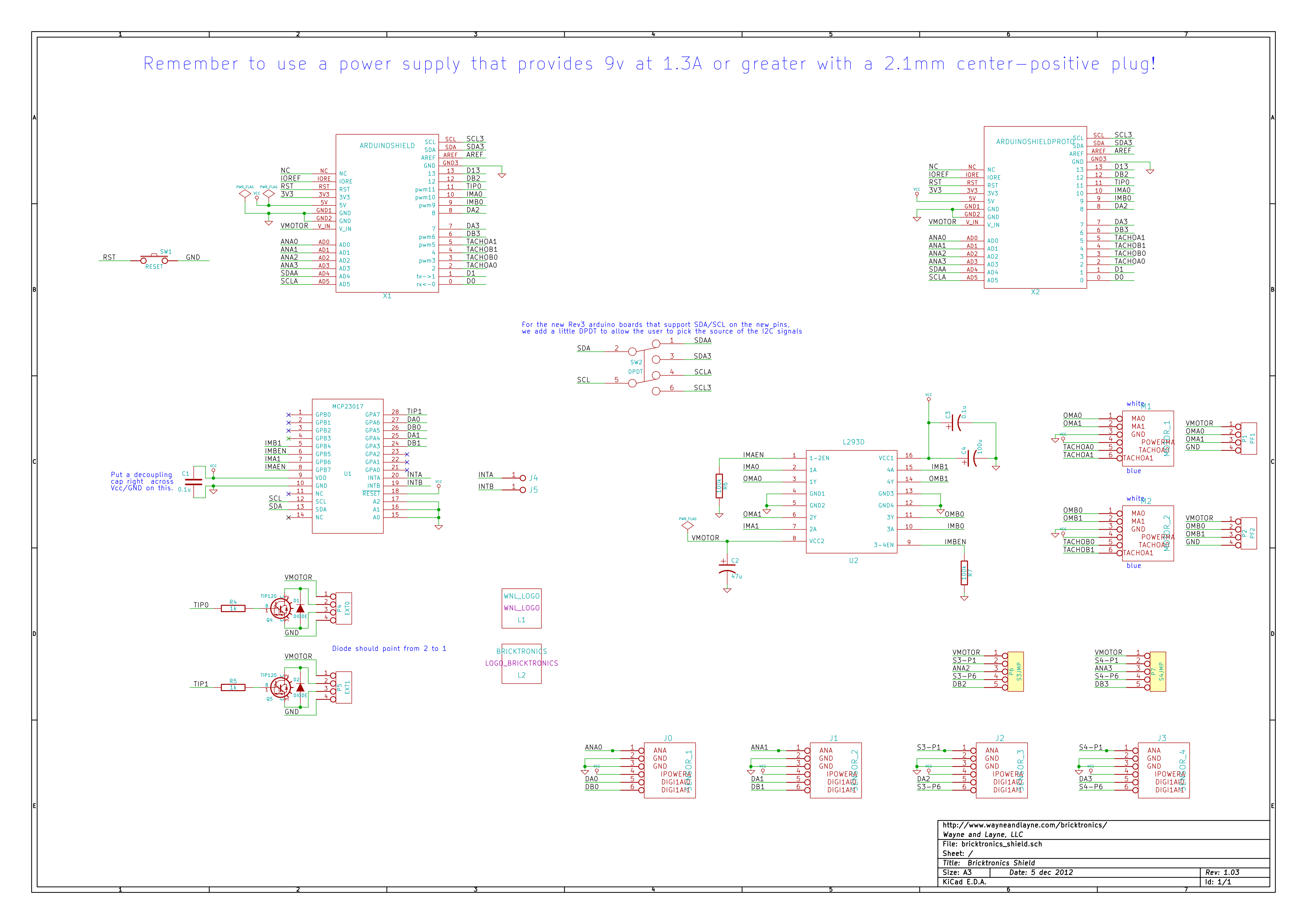
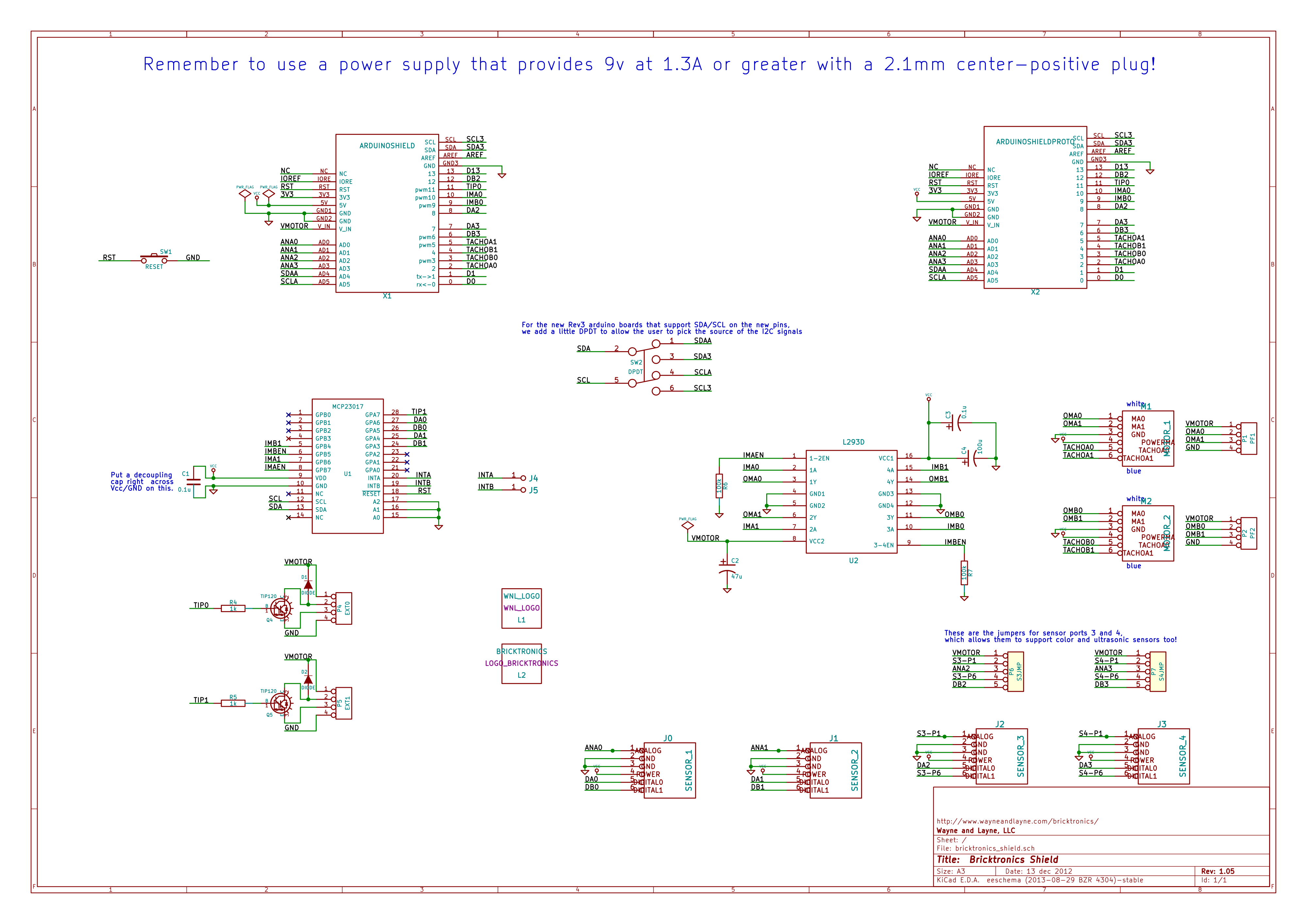
Arduino Pins
The Bricktronics Shield uses a lot of Arduino pins, but if you don’t use all the motors and sensors you can get away with reusing many of them. Here’s a pin mapping for the Bricktronics Shield, but you can also refer to the circuit schematics for more details.
Bricktronics Shield (all versions)
- 0 – not used
- 1 – not used
- 2 – Motor 1 encoder input 1
- 3 – Motor 2 encoder input 1
- 4 – Motor 2 encoder input 2
- 5 – Motor 1 encoder input 2
- 6 – Sensor 4
- 7 – Sensor 4
- 8 – Sensor 3
- 9 – Motor 2 PWM (speed)
- 10 – Motor 1 PWM (speed)
- 11 – TIP120 1 base input
- 12 – Sensor 3
- 13 – not used
- A0 – Sensor 1
- A1 – Sensor 2
- A2 – Sensor 3
- A4 – Sensor 4
- A5 – I2C SDA to the IO expander
- A6 – I2C SCL to the IO expander
We also have a page on Bricktronics Library Design and Theory.