


Parts List
Through-hole Parts List :: Surface-Mount (SMT) Parts List
Through-hole Parts List
- (1) Blinky Printed Circuit Board – PCB
- (1) 2xAA Battery Holder with Switch – BT1 (unlabelled)
- (8/56) Light Emitting Diodes (LEDs), 5mm – D1 through D8/D56
- (1) 14 pin chip socket – U1
- (1) PIC 16F1823 Microcontroller – U1
- (2) 10 kΩ resistors – R1, R2
- (2) Ambient Light Sensors – D, C
- (1) 0.1uF Ceramic Capacitor – C1
- (1) 6mm Pushbutton – SW1
Blinky GRID:
Blinky POV:
What does each part do?
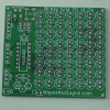
Blinky Printed Circuit Board (PCB) (Back to list)
The Blinky PCB is a professionally made printed circuit board to hold all the necessary parts. The PCB is a fully-custom design with two signal layers and no vias. All parts are through-hole for easy soldering, with full soldermask and complete silk-screen labelling of all parts. There is a separate PCB for POV and GRID versions of the Blinky Kit. You can download the schematic and PCB design files from the download page.

2xAA Battery Holder with Switch (Back to list)
The battery holder can hold two AA-cell batteries, used to power the various components of the Blinky kit.
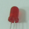
Light Emitting Diodes (LEDs), 5mm (Back to list)
An LED will light up when current is passed through it in a certain direction. Because they are diodes, current can only pass in one direction, meaning that LEDs are polarized parts and must be inserted into the PCB with a specific orientation. There are 8 LEDs in the Blinky POV kit, and 56 LEDs in the Blinky GRID kit. We use standard 5mm (T1-3/4) LEDs for the Blinky kits.
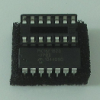
PIC 16F1823 Microcontroller and Socket (Back to list)
The PIC 16F1823 is a re-programmable microcontroller used to control the LEDs on the Blinky kit. It runs firmware written in both the C and Assembly (ASM) programming languages. The specific Microchip part number we use is PIC16F1823-I/P which is a through-hole DIP package. The socket is a way to connect the chip to the PCB without soldering the chip directly. By soldering the socket to the board instead of soldering the chip directly, there’s no possibility of overheating the chip with the soldering iron. The chip can also be removed or replaced without soldering.
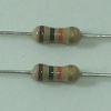
10 kΩ Resistors (Back to list)
The two resistors in the Blinky kit are used to help read values from the light sensors. They are standard through-hole resistors, 10 kΩ of resistance, 5% precision, 1/4 Watt.
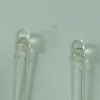
Ambient Light Sensors (Back to list)
The two ambient light sensors are used during the reprogramming and message transfer phases of operation. They are able to detect the brightness of light near the sensor. We activate the sensors by holding them up to a computer or smartphone screen and displaying black and white images. These alternating images are used to transfer new messages or programs to your Blinky kit’s microcontroller.
They are a 3mm LED-like package of the TEPT4400, made by Vishay Semiconductors. Here are the Mouser and Digikey product pages.
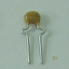
0.1 uF Ceramic Capacitor (Back to list)
The 0.1 uF ceramic capacitor is used to help smooth-out ripples in the power supply, a use commonly called a “de-coupling” or “bypass” capacitor, common to many projects.
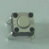
The push button is used for multiple purposes, including switching between messages and entering the reprogramming mode. The specific pushbutton we use is the B3F-1000 by Omron Electronics.
Surface-mount Parts List
- (1) Blinky Printed circuit board – PCB
- (1) CR2032 Battery holder – BT1 (unlabelled)
- (8/56) Light Emitting Diodes (LEDs), 5mm – D1 through D8/D56
- (1) PIC 16F1823 Microcontroller – U1
- (1) Pushbutton – SW1
- (2) 10 kΩ resistors – R1, R2
- (1) 0.1uF ceramic capacitor – C1
- (1) Power switch
- (2) Ambient light sensors – D, C
- (2) CR2032 lithium battery cell BT1 (unlabelled)
- (2) Butterfly clasp and pin back
Blinky Grid SMT:
Blinky POV:
What does each part do?
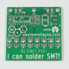
Blinky Printed Circuit Board (PCB) (Back to list)
The Blinky PCB is a professionally made printed circuit board to hold all the necessary parts. The PCB is a fully-custom design with two signal layers. We did our best to make the PCB easy to work with, both during assembly and during use. There is a separate PCB for the POV and Grid versions of the Blinky kit (as well as for the Blinky Through-Hole and the Blinky SMT kit!) You can download the schematic and PCB design files from the download page.
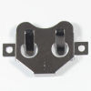
The battery holder holds a CR2032 coin cell battery, which provides power for the Blinky kit.
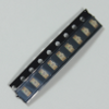
Light Emitting Diodes (LEDs), 1206 (Back to list)
An LED will light up when current is passed through it in a certain direction. Because they are diodes, current can only pass in one direction, meaning that LEDs are polarized parts and soldered to the PCB with a specific orientation. There are 8 LEDs in the Blinky POV SMT kit, and 56 LEDs in the Blinky Grid SMT kit, but we try to include some extras in case you misplace them during assembly. We use standard 1206 LEDs for the Blinky SMT kits.
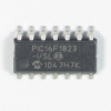
PIC 16F1823 Microcontroller, SOIC Package (Back to list)
The PIC 16F1823 is a re-programmable microcontroller used to control the LEDs on the Blinky SMT kits. It runs firmware written in both the C and Assembly (ASM) programming languages. The specific Microchip part number we use is PIC16F1823-I/SL which is an SOIC package.
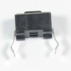
The push button is used for multiple purposes, including switching between messages and entering the reprogramming mode. The specific pushbutton we use is the PTS635SL43 LFS by C&K Components, but there are a variety of buttons with the same footprint.
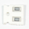
10 kΩ Resistors (1206) (Back to list)
The two resistors in the Blinky kit are used to help read values from the light sensors. They are 1206 surface mount resistors, 10 kΩ of resistance, 5% precision.
0.1 uF Ceramic Capacitor (1206) (Back to list)
The 0.1 uF ceramic capacitor is used to help smooth-out ripples in the power supply, a use commonly called a “de-coupling” or “bypass” capacitor, common to many projects. We use a 1206 package.
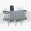
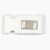
The two position switch controls the power from the battery. We use a JS102011SAQN by C&K Components.
Ambient Light Sensors (Back to list)
The two ambient light sensors are used during the reprogramming and message transfer phases of operation. They are able to detect the brightness of light near the sensor. We activate the sensors by holding them up to a computer or smartphone screen and displaying black and white images. These alternating images are used to transfer new messages or programs to your Blinky kit’s microcontroller.
They are a 3mm LED-like package of the TEPT4400, made by Vishay Semiconductors. Here are the Mouser and Digikey product pages.

CR2032 Coin-Cell Battery (Back to list)
The coin-cell battery fits into the battery holder on the back of the Blinky SMT circuit boards, and provides power to the circuit.
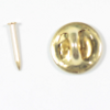
Pin back and clasp (Back to list)
If you want to wear your Blinky Grid SMT or Blinky POV SMT as a badge by pinning it to your shirt or a backpack, then you can use the included pin back and clasp. The pin is soldered in the larger hole in the top-center of the circuit board.