


Battery Booster Shield
Introduction :: Features :: PCB Assembly :: How it Works :: Use Cases :: Arduino Software :: Hardware :: Licensing :: Purchase
Introduction
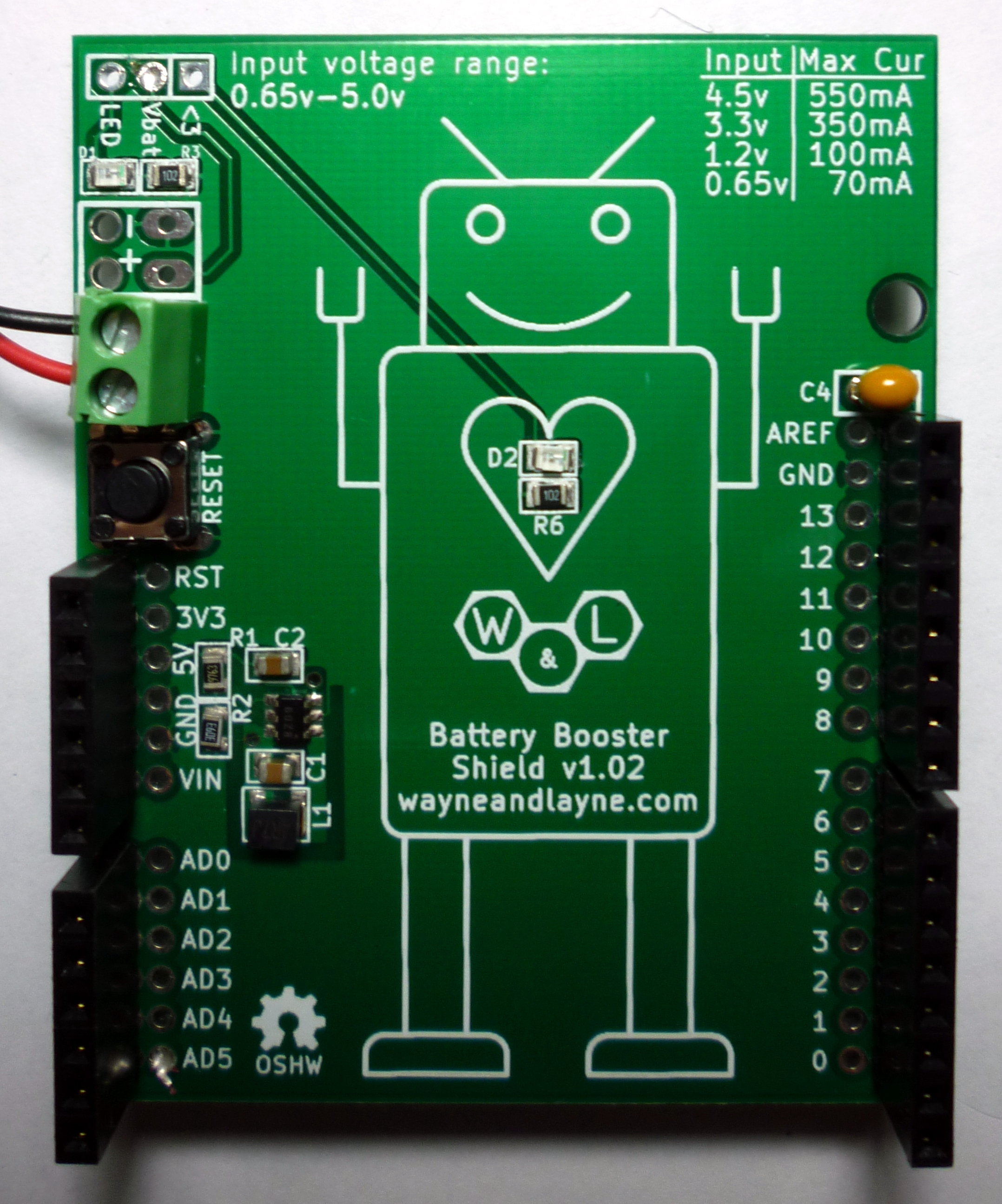
The Battery Booster Shield is an add-on for the Arduino that efficiently boosts a lower input voltage (0.65V to 4.5V) up to 5V. It powers the Arduino and peripherals through the 5V pin. The current limit is determined by the input voltage, and ranges from 70mA for 0.65V up to 550mA for 4.5V.
Features
- High Efficiency Power Conversion means that your batteries last longer, and deliver more useful power to your circuit. Traditional “drop-down” linear regulators waste excess power as heat, reducing your battery lifetime.
- Easy to assemble kit only requires basic soldering of a few simple components. Most of the parts are pre-soldered.
- Fully open-source design means that everything is freely available and ready to be hacked, including the circuit schematic, circuit board layout, parts list, and Arduino sketches.
- Custom, professionally-made PCB provides easy connections to all buttons and the Arduino Mega, and has been specially designed to work in two configurations, either normal or upside-down.
PCB Assembly
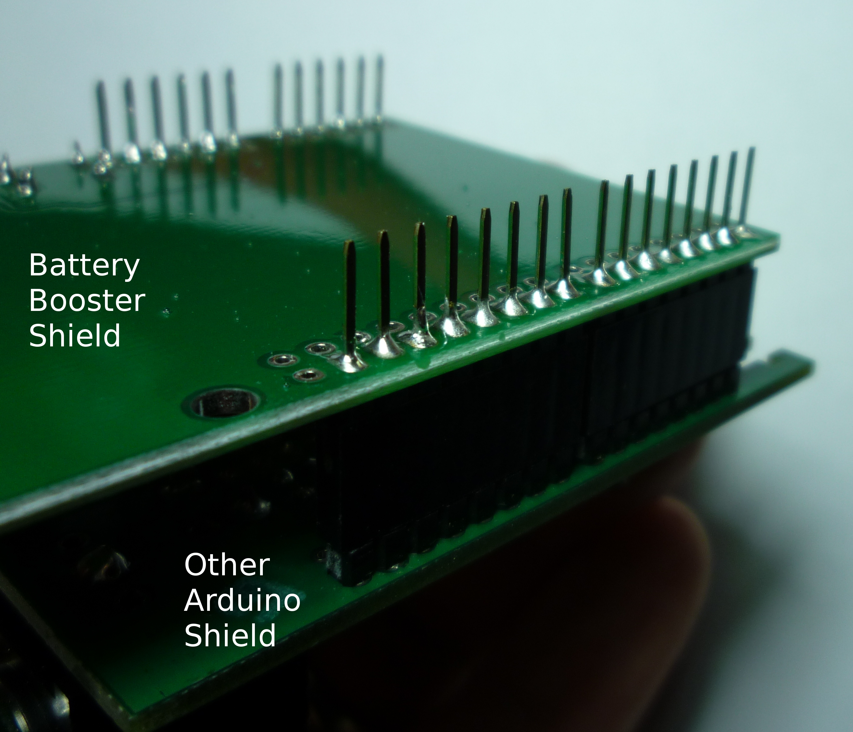
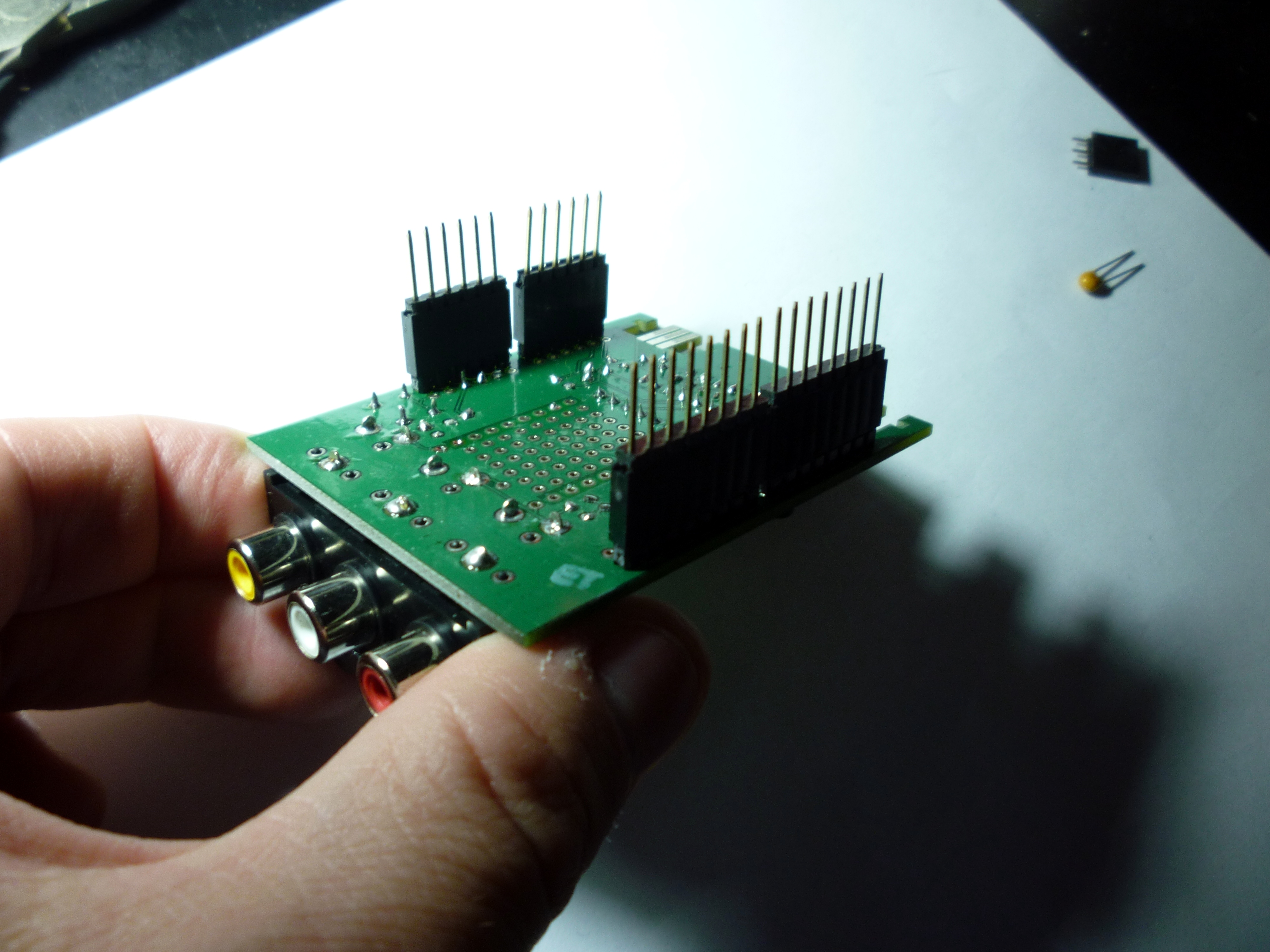
Most of the soldering is already finished for the Battery Booster Shield, but you will need a soldering iron and solder to finish soldering the kit. The header pins to connect the shield to the Arduino need to be soldered in. To do this, grab any Arduino shield, and stick the included long header pins to the pins on the spare shield. This will allow us to make sure the header pins are nice and straight. Slide the Battery Booster Shield onto the long header pins, making sure the components are facing away from the exposed pins. Solder the pins to the shield.
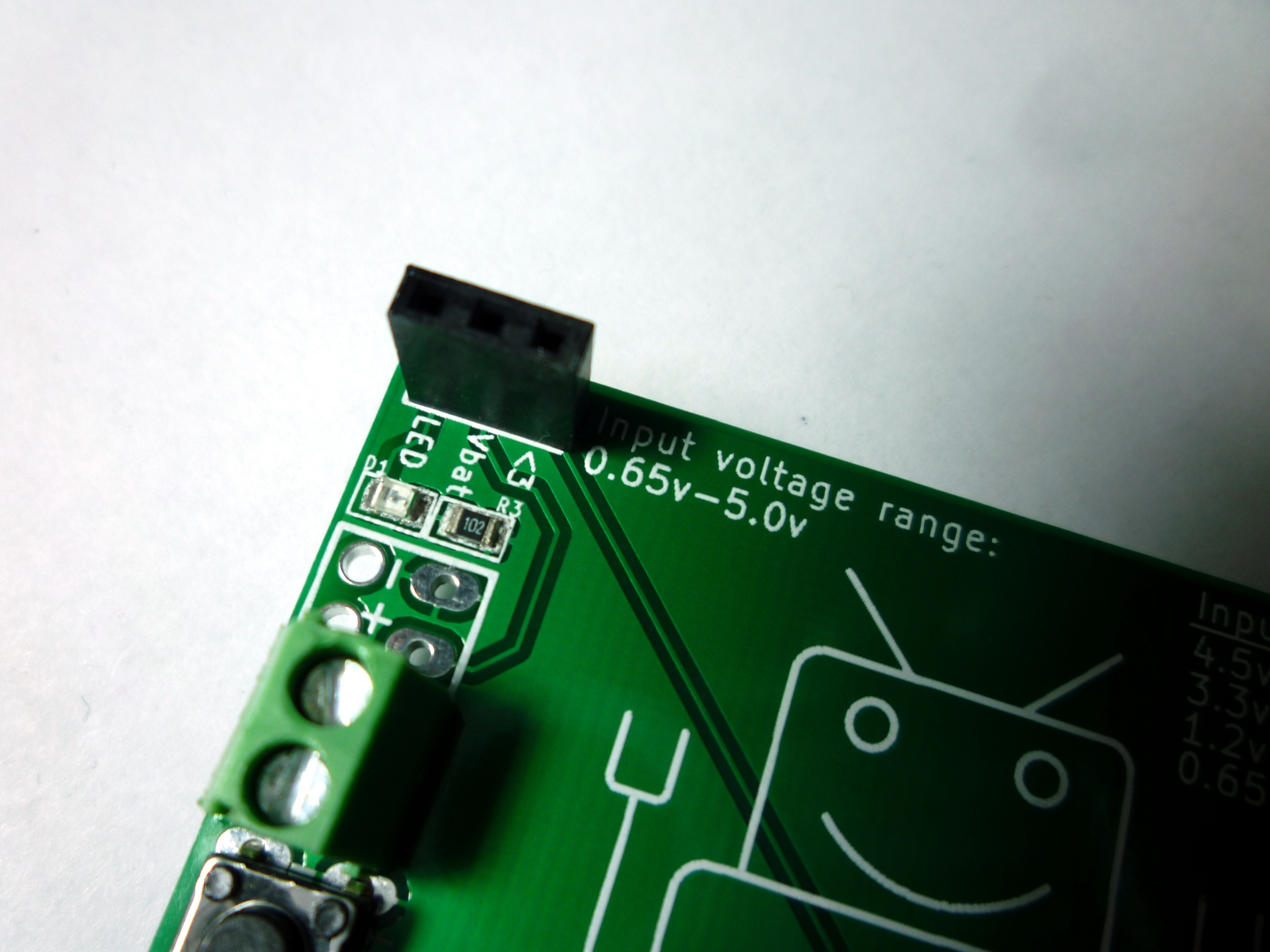
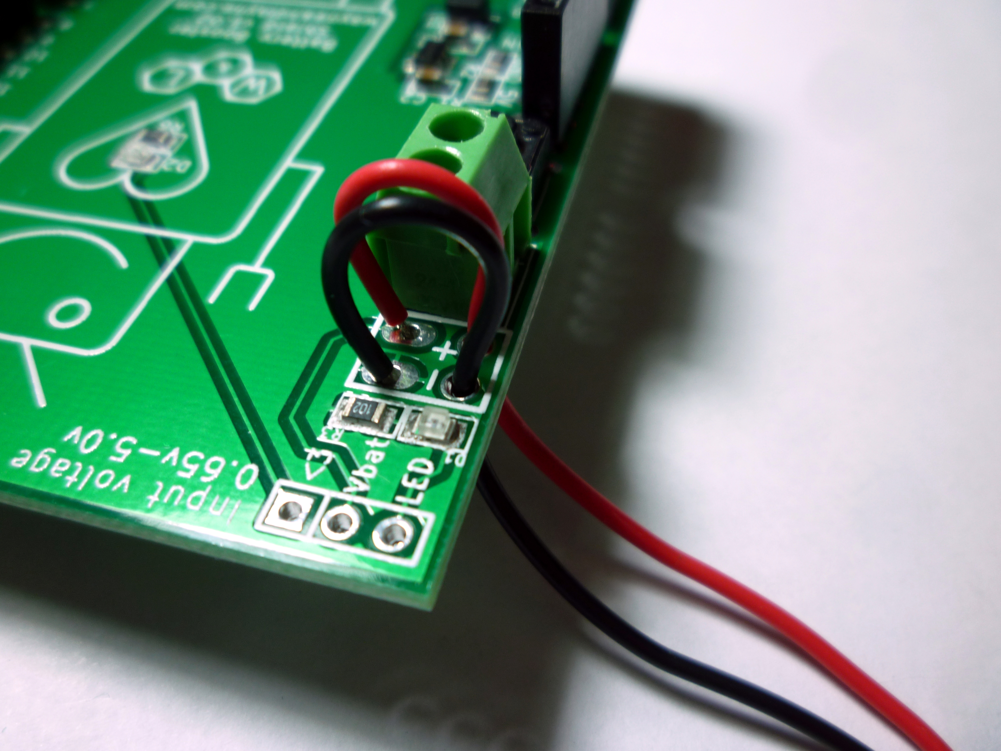
The Battery Booster Shield includes a mini expansion header with three connections, located in the lower-left corner of the shield. The bottom pin is a connection for the LED next to it, the middle pin is a direct connection to the battery voltage, and the upper pin is for the “heart LED” in the center of the shield. You can use a little piece of wire to connect the LED pins to any arduino pin you want, and control the LEDs in software. You might use one led as a power indicator, or perhaps a blinking “low battery” alert. The center pin connects to the battery voltage, and you can connect this pin to any of the analog input pins to be able to monitor your current battery voltage. If you want to use any of these three connections, you can either solder wires directly into the holes, or you can install the included 3-pin female header pins, to allow you to reconfigure the connections.

To supply the input voltage to the Battery Booster Shield, there are two options. If you want a more permanent connection from your batteries to the shield, you can solder the battery leads to the provided pads as shown below in the image on the left. Pass the wires through the strain-relief holes and then back down into the actual holes, and solder them in place. For a less permanent connection, you can use the screw-down terminal block between the solder holes and the reset button. Simply observe the positive and negative signs below each terminal, unscrew the terminal to open it up, insert your wire, and screw it down to secure the wire.

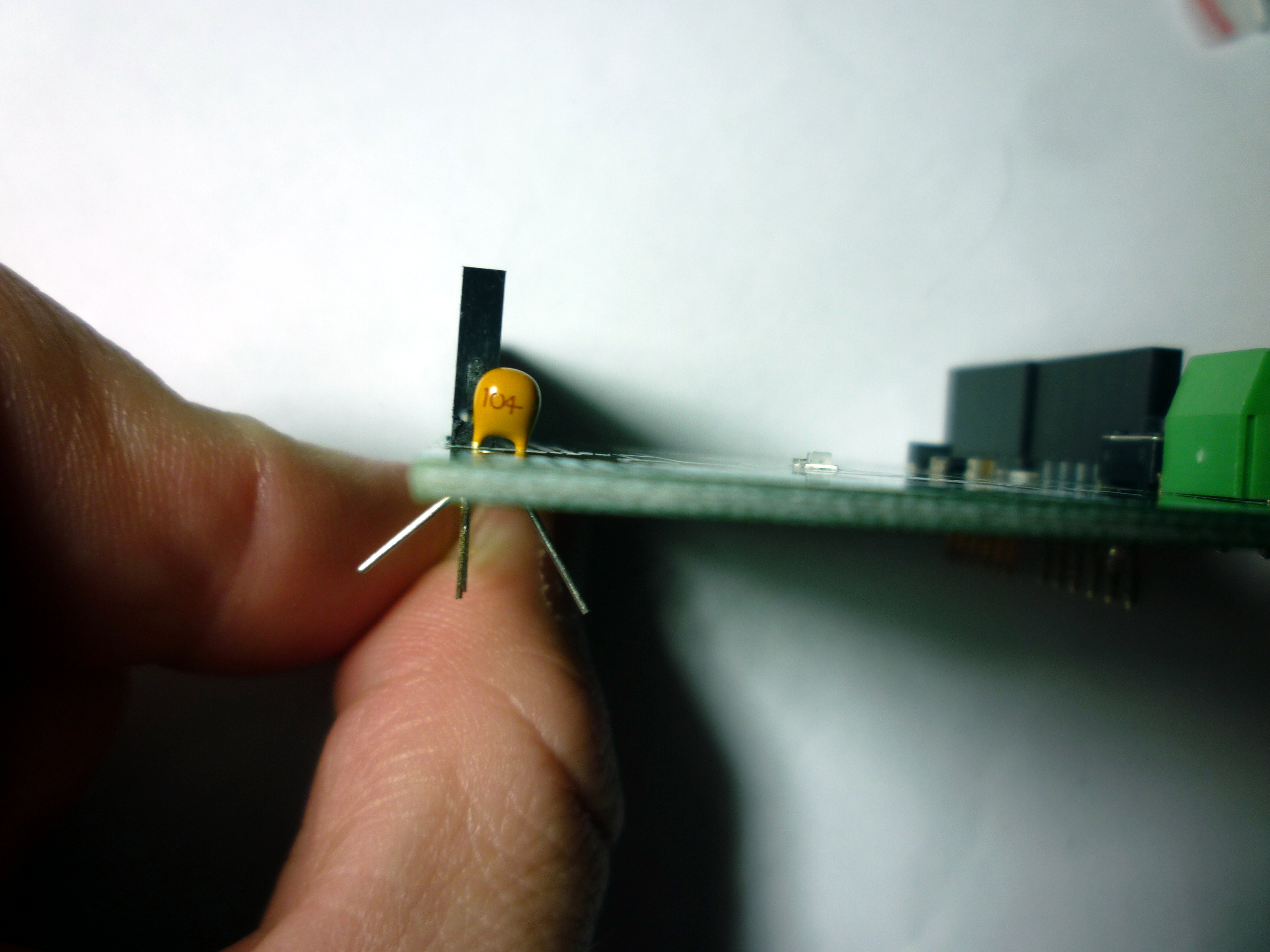
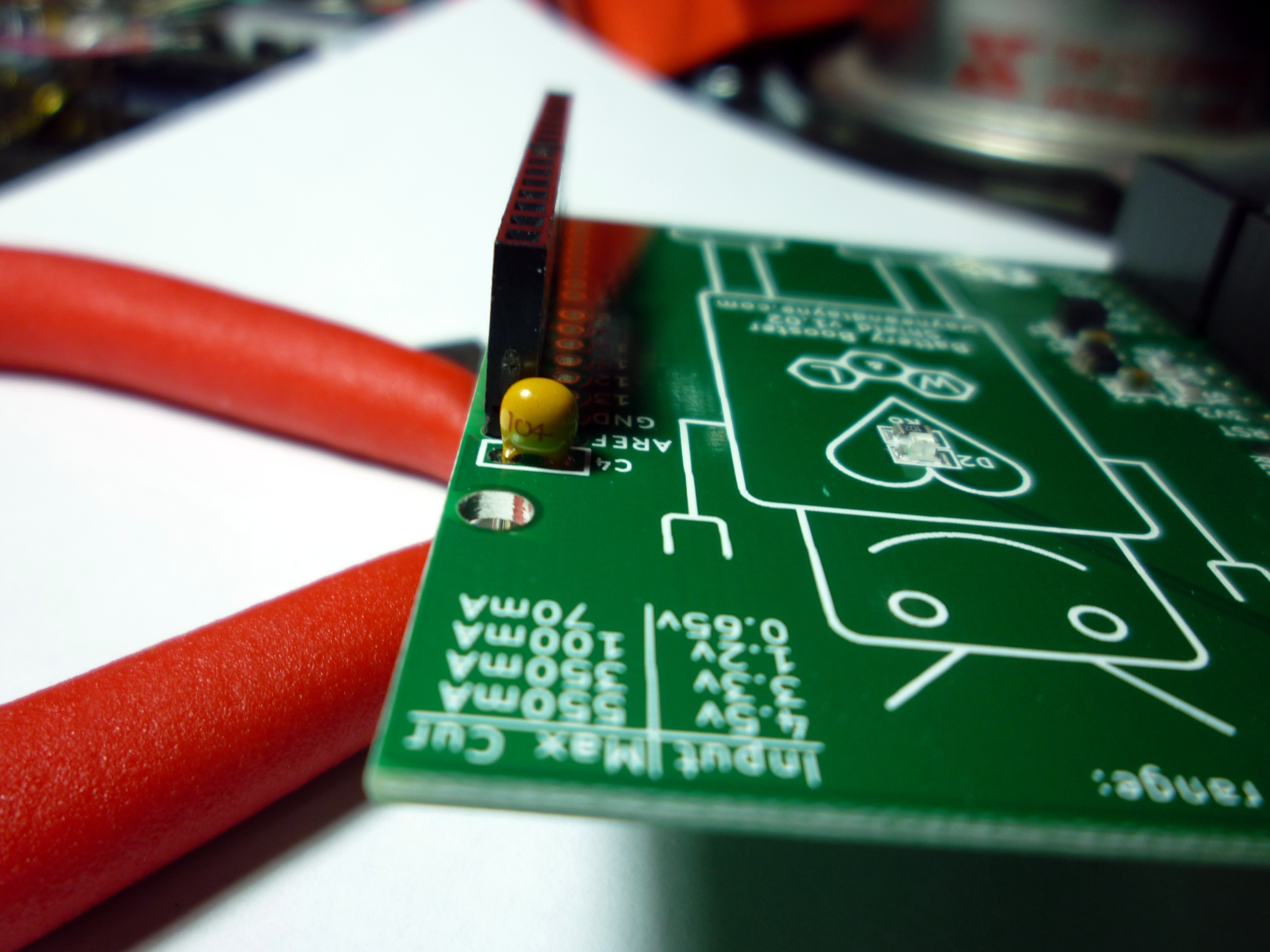
If you are going to use the Vbatt connection with an analog pin to measure the battery voltage, for example to shut down your circuit before you damage your rechargeable batteries, you probably want to add the small capacitor included with the kit. This capacitor is located next to the Aref pin on the top side of the shield, and is labeled C4. This capacitor helps the Arduino’s analog-to-digital converter (ADC) make more-accurate measurements of the voltage using an analog pin. To install it, simply insert the capacitor into the labeled holes, bend the holes slightly to keep it from falling out, solder down the pins, and trim the excess wires.
Demonstration Use Cases
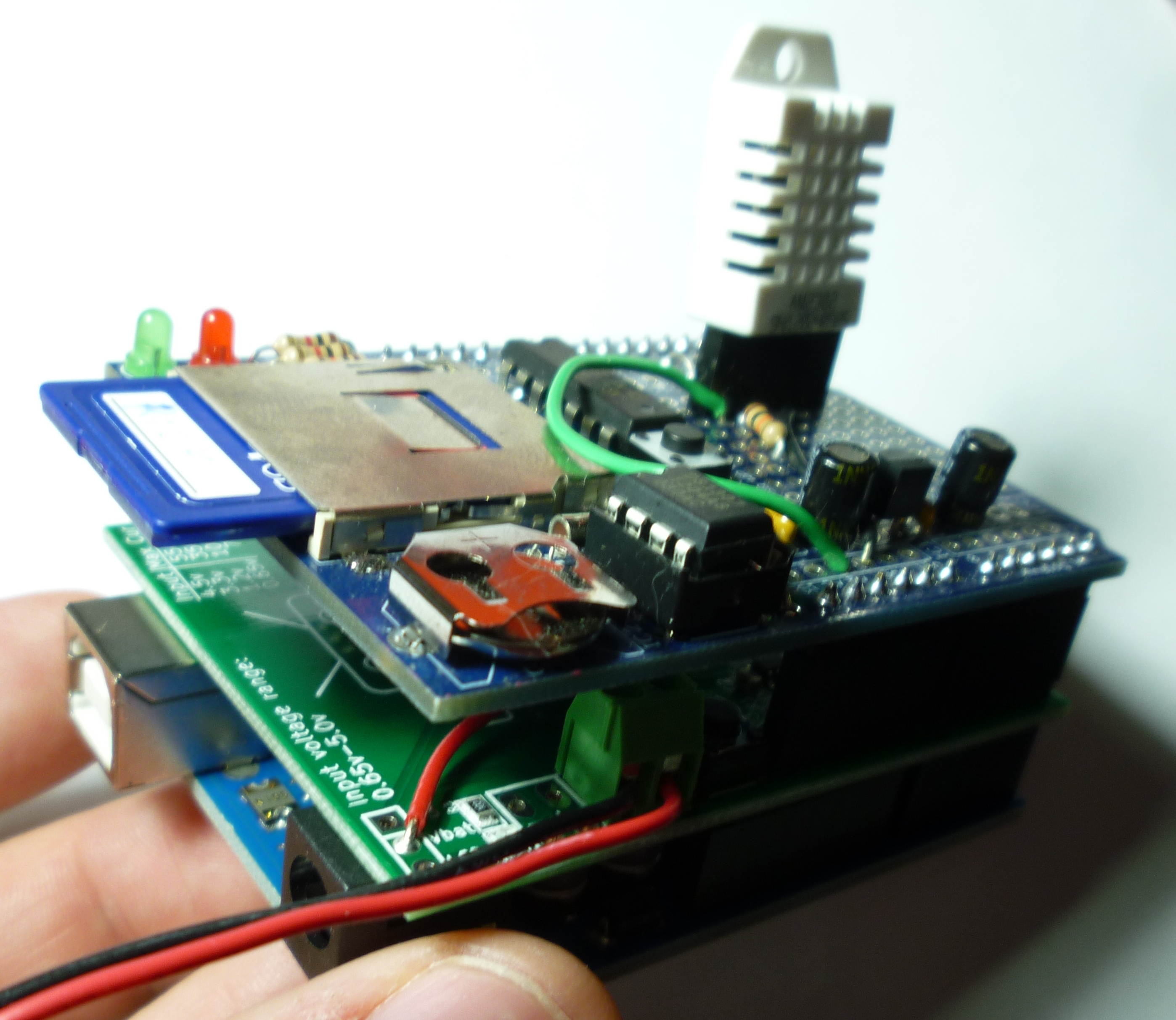
Low-Power Data Logger – Being a very efficient voltage booster, the Battery Booster Shield works very well for long-term and low-power data logging applications. Using special commands to set the Arduino to sleep for a few seconds at a time, we can really save a lot of power and make the batteries last for a long time. This would be very useful for a low-power remote sensor node or data logging device.
LoL Shield Power Supply – TODO
How it All Works
When powering an arduino from 6 volts or higher through the DC jack, any voltage in excess of 5 volts is simply wasted as heat in the voltage regulator on the Arduino board. It is simple to figure out the amount of power wasted by the simple “linear” voltage regulator, it is simply the voltage drop across the regulator multiplied by the amount of current drawn by your circuit. For example, powering your Arduino with a 9v battery will drop 9 – 5 = 4 volts in the regulator. If you circuit draws 100 milliamps (mA), then 4v * 0.1A = 0.4 watts of power wasted in the regulator, and 5v * 0.1A = 0.5 watts of power are delivered to your circuit. In this example, of the 0.9 watts of power drawn from the battery, 0.4 watts (over 44%) of power is wasted as heat! This leads to an efficiency of less than 66%.
The Battery Booster Shield can drastically improve the efficiency of your battery use by using a high-frequency switching circuit to boost a lower voltage up to a nice 5 volts for use by your Arduino. The core idea of a boost DC-to-DC converter is shown in the circuit figures below, with the lower-voltage supply on the left running through an inductor, with a diode in line with the load.
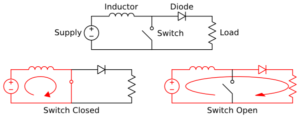
When the switch is closed, current flows from the lower-voltage voltage supply through the inductor. An inductor is simply a small coil of wire, which generates a magnetic field when current flows through the coil. The key property of an inductor is that it resists changes in the coil current, due to the magnetic field. When the switch changes from “closed” to “open”, the inductor sustains the flow of current through the diode and into the load. If this switching happens fast enough, a voltage is generated at the load that is larger than the supply voltage.
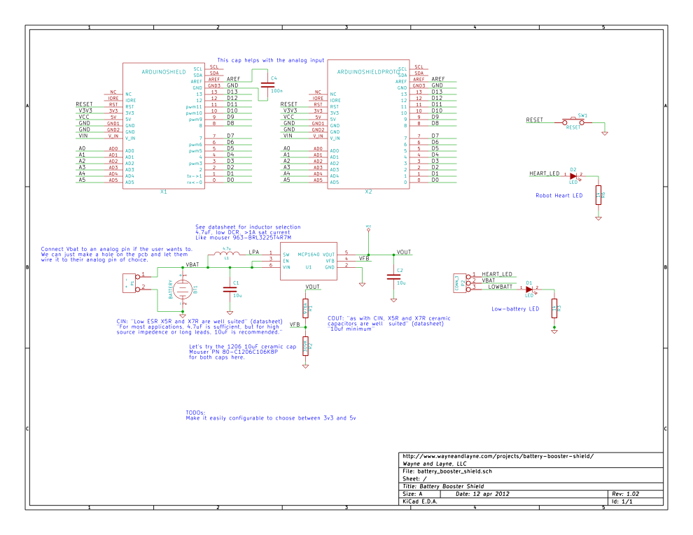
The Battery Booster Shield is based on the MCP1640 chip from Microchip Technology. This chip contains the high-speed switching circuitry needed by the boost converter. While this chip has an adjustable output voltage that can be set anywhere between 2.0 and 5.0 volts, we have used two resistors on the Battery Booster Shield circuit board to fix the output voltage to 5.0 volts. More details about the inner workings of this boost converter chip, suggested circuit designs, etc, are available in the MCP1640 datasheet, and two companion application notes:
- AN1337 – Optimizing Battery Life in DC Boost Converters Using MCP1640
- AN1311 – Single Cell Input Boost Converter Design
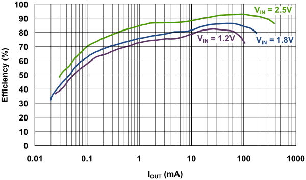
As mentioned before, efficiency is an important measure of how good our converter is. For 5v output, this is the efficiency at three different values of input voltage, for a wide range of output current. We see that for 2.5v, which is approximately what you would get from a pair of alkaline AA cells, the converter will have greater than 90% efficiency when drawing anywhere between 20mA and 250mA.
TODO: explain more about the battery sensing concepts, and the Vref cap, with some sample code, etc
Arduino Software
- Adafruit’s DHT library, modified for datalogging
- Rocketscream’s low-power library, slightly modified
- Adafruit’s RTC Library
- Adafruit’s SD and FAT library
Hardware
The Battery Booster Shield was developed with Kicad, an open source electronic design suite. It is available for Windows, Linux, and OSX.
Both the original plaintext design files for KiCad, as well as the production-ready gerber files, are available for download from the Wayne and Layne Github repository. Direct links are provided for some files below.
- All Battery Booster Shield design files (PCB v1.02) (ZIP)
- Battery Booster Shield Schematic (SVG)
- Battery Booster Shield Schematic (PNG)
Licensing
![]()
We consider the Battery Booster Shield to be open source hardware. All files are licensed Creative Commons Attribution-Share Alike 3.0.
This means you may copy, distribute, and display the files (and any modifications or “derivative works” you make) if you give credit to Wayne and Layne, LLC, link back to this website, and you must also license any modifications or derivative works under this exact same Creative Commons Attribution-Share Alike 3.0 License.
Battery Booster Shield by Wayne and Layne, LLC, is licensed under a Creative Commons Attribution-Share Alike 3.0 License.
Different licensing may be available. Contact us for more information.
Purchase
The Battery Booster Shield is available exclusively through the Maker SHED store, but we’ll add it to the Wayne and Layne store very soon!