


Tap-Tempo Metronome 2 – External Connections
One of the features we wanted to add when re-designing the original metronome kit was to make it much easier for people to hack the kit, and add external connections. To this end, we added six header pin connections at the bottom of the circuit board:
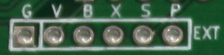
The rest of this post will be an explanation of what each of those pins is doing.
- Pin G – This pin is the ground connection, tied to the negative terminal of the battery holder. All signals are voltages measured relative to this ground.
- Pin V – This pin is the voltage connection, tied to the positive terminal of the battery holder when the power switch is in the “on” position. This can be useful if you want to draw a bit of voltage to power your external hardware.
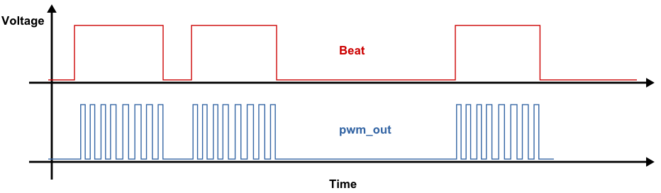
- Pin B – This pin is the beat connection. The pin goes high (is equal to the V pin’s voltage) whenever the kit is beeping (for the duration of each beep). It outputs a solid (non-PWM) signal. This signal might be useful to trigger external lights or motors or sequencers or synthesizers, etc.
- Pin X – This pin is a spare GPIO pin on the microcontroller, specifically it’s pin 3 named RA4. We didn’t have anything to use it for, but we added it to this header in case you want to hack the firmware to do something cool with it.
- Pin S – This pin is the synchronize pin, which could someday be useful for connecting multiple metronomes together with a common timebase. We didn’t end up creating a way for you to connect multiple metronomes, but we thought it would be pretty cool to set one metronome going, then use the sync pins to allow the other metronomes to keep in sync with the “master” metronome started first. As it is, this pin is similar to the spare pin (labeled X), as it’s just connected to a GPIO pin on the microcontroller, specifically it’s pin 12 named RB5.
- Pin P – This pin is the PWM output from the microcontroller that is used to drive the on-board piezo buzzer. If you want to make an external piezo beep, this is the pin for you, just connect the piezo between pin P and pin G (ground) and it should beep. The output signal is a 4 kHz square wave whenever the kit is beeping. If you want to disable the on-board piezo from beeping, check out the instructions here for which trace to cut.
Here’s a graphical explanation of the difference between the B “beat” and P “pwm_out” signals:
There are some more photos and information about external connections in the W&L Discussion forum.
You may also be interested in the circuit schematic (PNG).
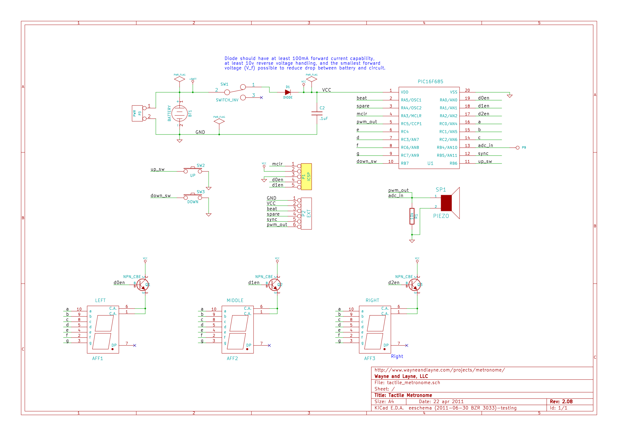
2 Comments
Leave one →
Under
x Pin S – … As it is, this pin is similar to the sync pin…”
Isn’t this the sync pin? Should it be “As it is, this pin is similar to the beat pin…” ? Or am I misunderstanding?
thanks
-k
Kaizaad, thank you for the comment. You are 100% correct, thank you for noticing my mistake. I have fixed the text in the blog post.